
Wood
Chris-Craft Cobra pt 2
30 - July - 2016 - 12:43
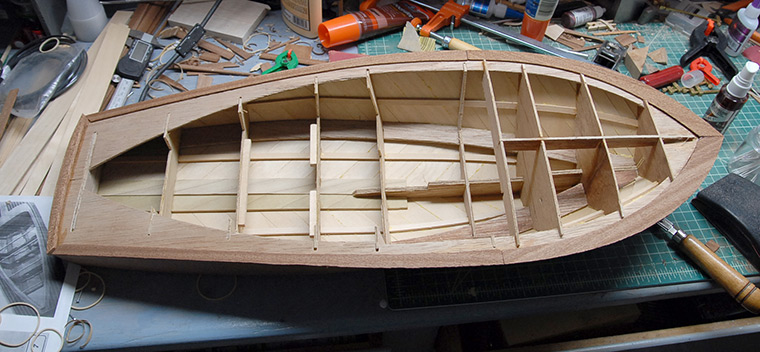
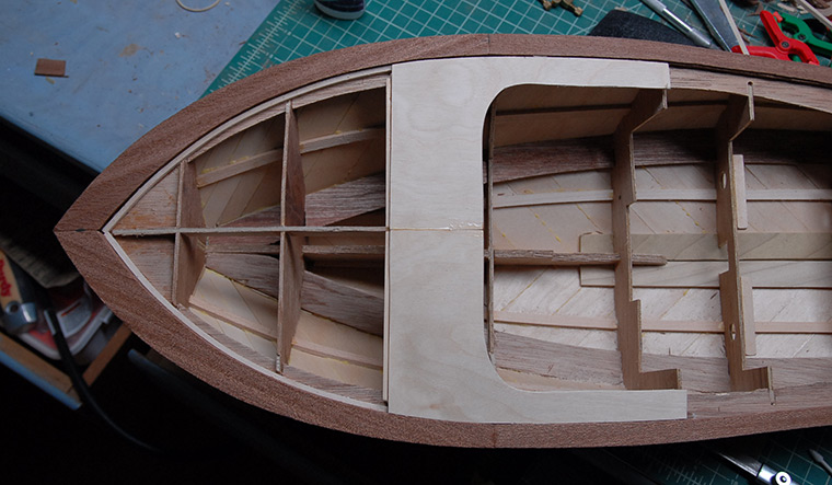
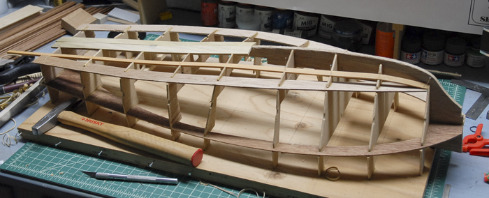
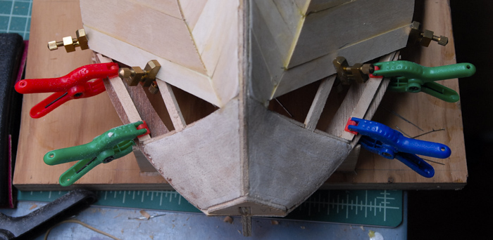
In the last post, I had just wrapped up the under-planking. Next came the mahogany planking. I began on the keel, running a plank up each side of the center line on the bottom. I also soaked some of the planks, so that they would be easier to bend at the front. Below you can see the darker plank (dark because it is wet), bent around the front of the keel.
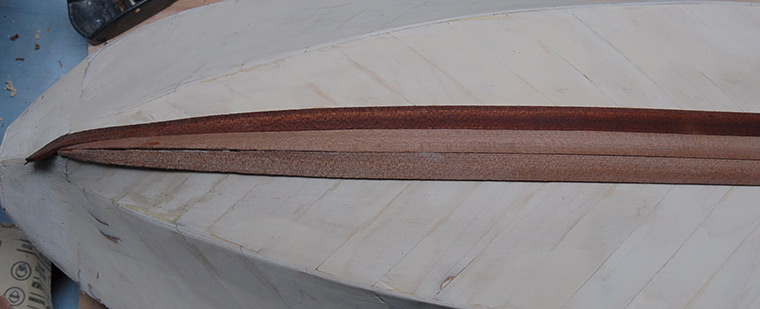
After a few rows of planks from the center, I then added one that runs along the edge that forms the border between the bottom and the sides. Having that plank in place gave me something to fit the bottom planks to, so there isn’t a gap.
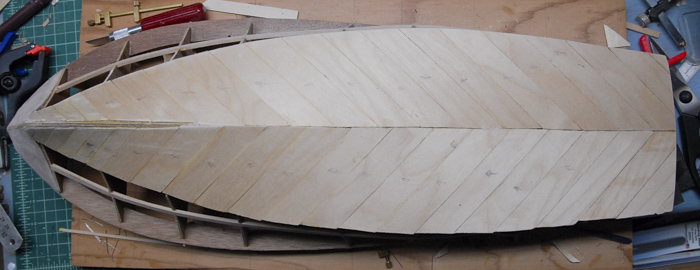
Below you can see the bottom planking done. The planks are just glued on with thick CA glue, so they go on fairly quickly.
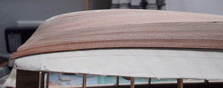
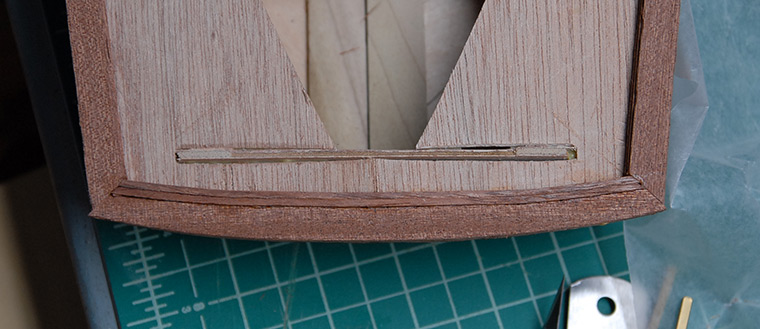
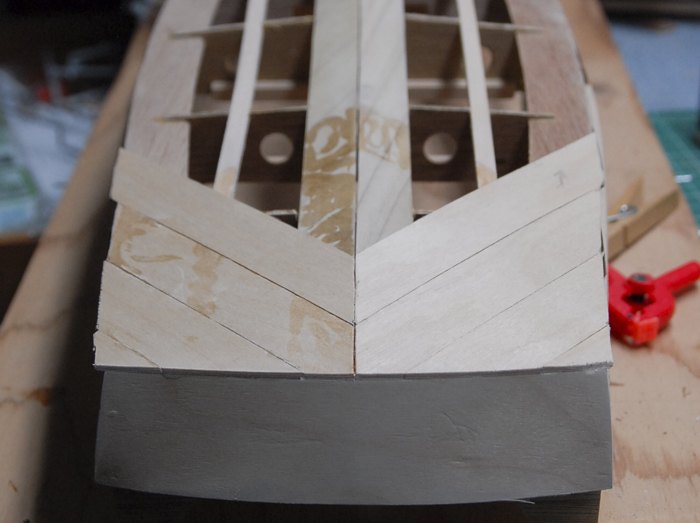
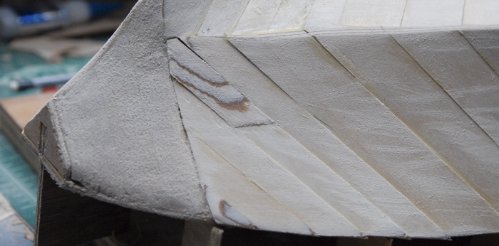
Below you can see a detail shot of the front. I wasn’t too careful about the fitment on these planks, as they will be below the waterline and therefore painted. With a little filler and sanding, this area will be nice and smooth before it gets painted.
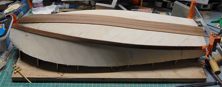
The planking continued on the sides of the boat. The planks were long enough to span the length of the boat, so attaching them really just consisted of tracing a line along the edge of each plank on the hull (seen below), and then using that line as a guide for where to apply some glue. With the glue in place, then I can just hold the plank in place until the glue sets.
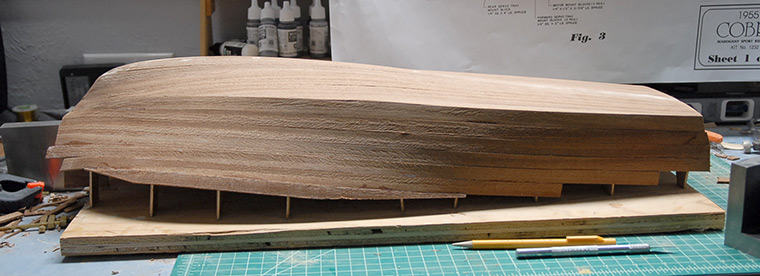
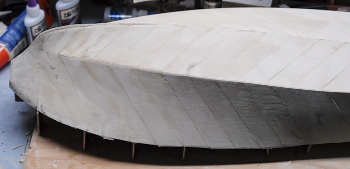
Below you can see all the bottom and side planks in place.
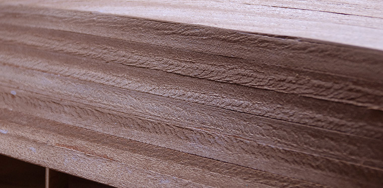
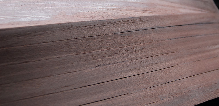
Here is a close-up showing the relatively rough surface of the planks. This will take quite a bit of sanding later to get it smoothed out.
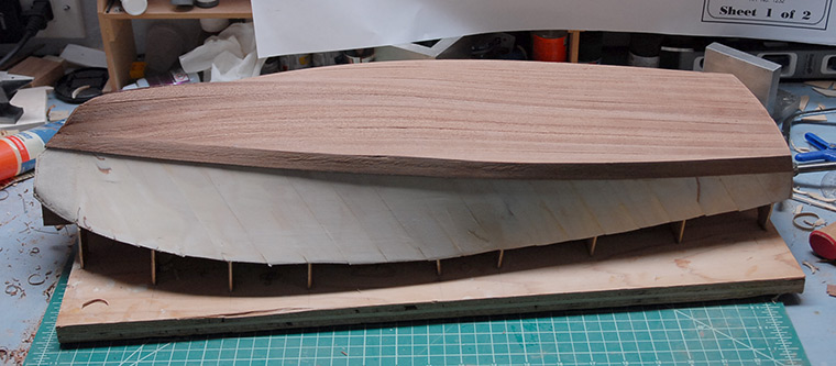
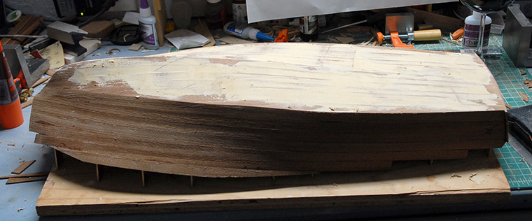
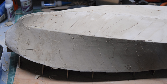
With all the planking in place, I applied a coat of the wood filler to the lower parts of the hull. This is the area that will later be painted, so having a smooth surface is more important than having good looking wood.
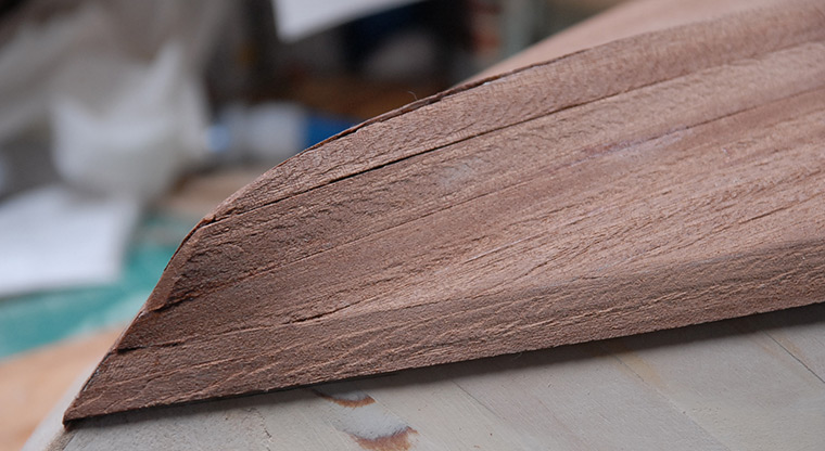
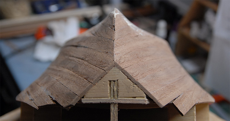
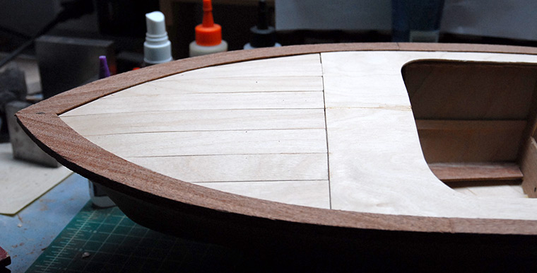
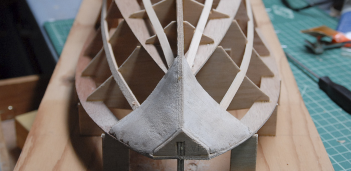
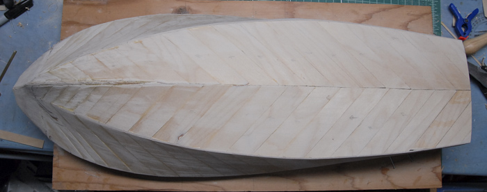
Below you can see the nose of the hull after a bit of sanding and refining of the center line.
It was also at about this point that I realized that maybe soaking the big mahogany planks was not the best thing to do. It seems that while the planks being wet made them easier to bend around a few curves, it also made them swell just a bit. Once the planks had been on the hull for a few days and had dried out, they shrunk back to their original size, leaving a few gaps between the planks. I’m hoping that these will be filled in a bit later on, once I put a bunch of coats of spar varnish on the hull.
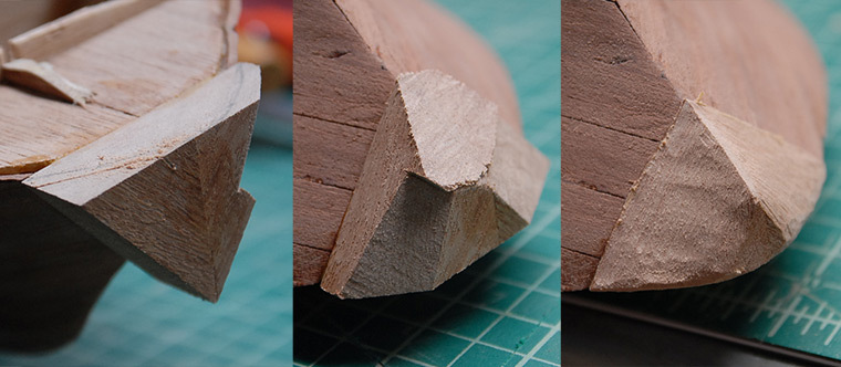
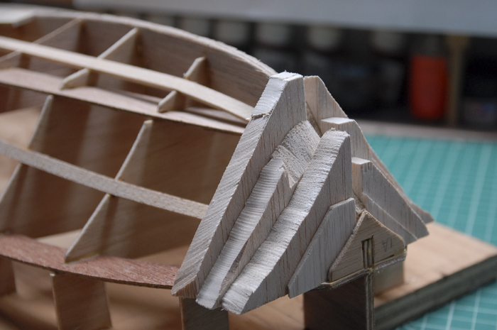
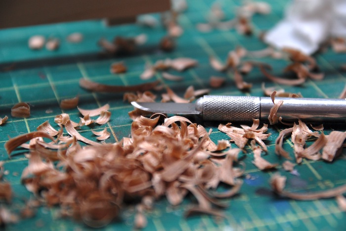
Next up was carving the nose from a block of mahogany. Below you can see the starting point, which was two triangles glued together, a mid point, when I had sawn off big chunks for rough shaping, and the point at which I had finished the rough shaping using a Dremel and sanding drum.
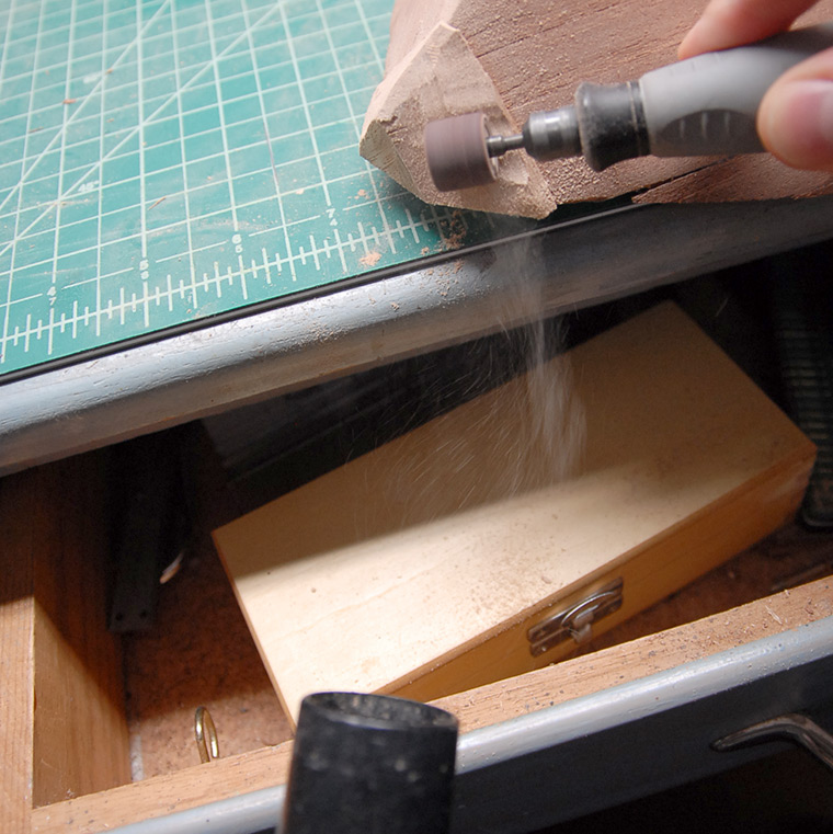
In order to reduce the mess from the sanding, I had some luck making a makeshift dust collection system using out vacuum cleaner hose positioned near the sanding. Below you can see an action shot of the sawdust coming off of the sanding drum and into the hose. It looked cool, so I took a photo :)
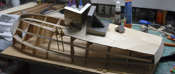
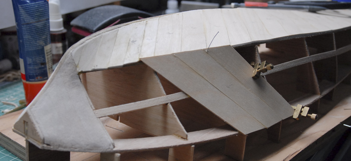
That completed the underside of the boat. The next step was to cut it off of the build board, sand the ribs flush with the top surface and then start adding the top deck components. Below you can see the edge parts glued in place. This was, unfortunately, where I made a bit of a mistake, placing the side strips a little bit too far inboard. I didn’t notice the misplacement until later in the build, though.
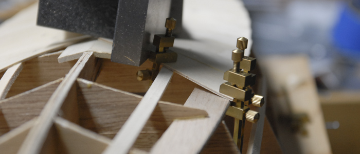
The side strips consist of three layers, each layer overlapping the others differently. Below you can see the second layer being held in place while the glue dries.
There is a strip that runs along the inside of the mahogany parts that provides support for the decking later. Below you can see it being glued in place.
In gluing the above strip in place, I realized my mistake. The rear edge strip was in the correct place, but when I glued the side strips on, I had aligned the outside edges with the outside of the rear strip, when I SHOULD have aligned the inside edges. Once I discovered this, I found that I couldn’t pry off the side strips without doing lot of damage, so I opted instead to make adjustments to the build as I went, in order to compensate for the misalignment. The first thing I had to do was add a few extra strips to the back in order to even out the alignment of the inside edge. Below you can see the two additional strips, before sanding.
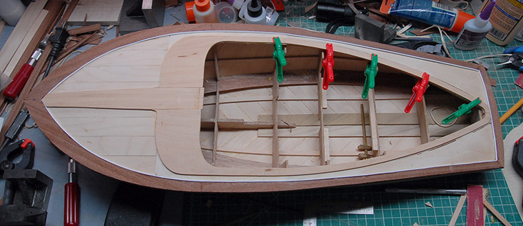
While there will need to be more adjustments later, the next few steps were fairly straightforward. Below you can see some decking glued in place, forming the front of the cockpit surround.
Front sub-planking in place, using the same techniques as the lower hull:
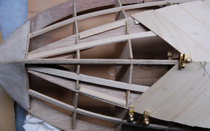
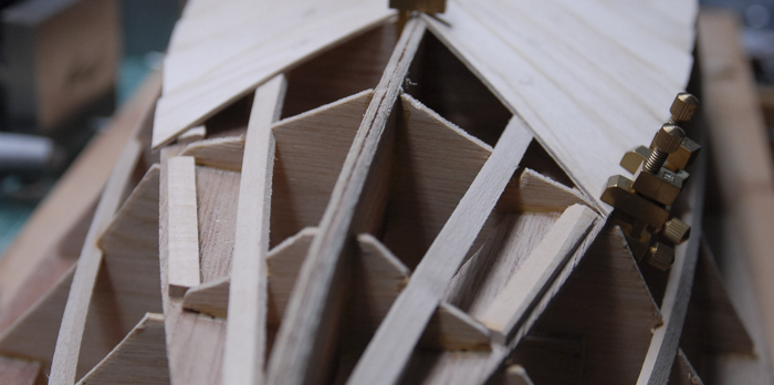
I order to provide support for the rear and side decks, I needed to add some support ribs. Theses were just 1/8” basswood, cut to length and tapered a bit so that there will be a bit of a slope to the decks.
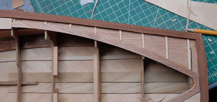
Below you can see the side/rear sub-decking in place. I had to do a good deal of trimming and fitting to this piece in order to fit it into a space that is slightly smaller due to my additional thickness on the rear edge piece.
Finally, once the sub-deck was in place, I could start to add the final top decking layer. Below you can see the current state of the boat. Because the side rails should have been pushed just a bit back and out, the center basswood part didn’t reach the full length of the front deck. This meant that I had to add a little piece to extend it, which will be sanded and integrated more later. The thicker rear edge rail also required that the large basswood part be shortened slightly, in order to match up with the edges of the cockpit and still just meet the rear edge. I ended up removing approximately 1/4 inch from the straight section along the edge of the cockpit. I may also need to shorten the plastic molded pieces that form the engine cover and fin, but I was already thinking of cutting those up in order to add opening engine bay covers, so that may not cause any problems.
That is where the project stands now. Next up is applying the striped mahogany and plastic decking, and then a bunch of sanding to even it all out.
Thanks for reading!
After a few rows of planks from the center, I then added one that runs along the edge that forms the border between the bottom and the sides. Having that plank in place gave me something to fit the bottom planks to, so there isn’t a gap.
Below you can see the bottom planking done. The planks are just glued on with thick CA glue, so they go on fairly quickly.
Below you can see a detail shot of the front. I wasn’t too careful about the fitment on these planks, as they will be below the waterline and therefore painted. With a little filler and sanding, this area will be nice and smooth before it gets painted.
The planking continued on the sides of the boat. The planks were long enough to span the length of the boat, so attaching them really just consisted of tracing a line along the edge of each plank on the hull (seen below), and then using that line as a guide for where to apply some glue. With the glue in place, then I can just hold the plank in place until the glue sets.
Below you can see all the bottom and side planks in place.
Here is a close-up showing the relatively rough surface of the planks. This will take quite a bit of sanding later to get it smoothed out.
With all the planking in place, I applied a coat of the wood filler to the lower parts of the hull. This is the area that will later be painted, so having a smooth surface is more important than having good looking wood.
Below you can see the nose of the hull after a bit of sanding and refining of the center line.
It was also at about this point that I realized that maybe soaking the big mahogany planks was not the best thing to do. It seems that while the planks being wet made them easier to bend around a few curves, it also made them swell just a bit. Once the planks had been on the hull for a few days and had dried out, they shrunk back to their original size, leaving a few gaps between the planks. I’m hoping that these will be filled in a bit later on, once I put a bunch of coats of spar varnish on the hull.
Next up was carving the nose from a block of mahogany. Below you can see the starting point, which was two triangles glued together, a mid point, when I had sawn off big chunks for rough shaping, and the point at which I had finished the rough shaping using a Dremel and sanding drum.
In order to reduce the mess from the sanding, I had some luck making a makeshift dust collection system using out vacuum cleaner hose positioned near the sanding. Below you can see an action shot of the sawdust coming off of the sanding drum and into the hose. It looked cool, so I took a photo :)
That completed the underside of the boat. The next step was to cut it off of the build board, sand the ribs flush with the top surface and then start adding the top deck components. Below you can see the edge parts glued in place. This was, unfortunately, where I made a bit of a mistake, placing the side strips a little bit too far inboard. I didn’t notice the misplacement until later in the build, though.
The side strips consist of three layers, each layer overlapping the others differently. Below you can see the second layer being held in place while the glue dries.
There is a strip that runs along the inside of the mahogany parts that provides support for the decking later. Below you can see it being glued in place.
In gluing the above strip in place, I realized my mistake. The rear edge strip was in the correct place, but when I glued the side strips on, I had aligned the outside edges with the outside of the rear strip, when I SHOULD have aligned the inside edges. Once I discovered this, I found that I couldn’t pry off the side strips without doing lot of damage, so I opted instead to make adjustments to the build as I went, in order to compensate for the misalignment. The first thing I had to do was add a few extra strips to the back in order to even out the alignment of the inside edge. Below you can see the two additional strips, before sanding.
While there will need to be more adjustments later, the next few steps were fairly straightforward. Below you can see some decking glued in place, forming the front of the cockpit surround.
Front sub-planking in place, using the same techniques as the lower hull:
I order to provide support for the rear and side decks, I needed to add some support ribs. Theses were just 1/8” basswood, cut to length and tapered a bit so that there will be a bit of a slope to the decks.
Below you can see the side/rear sub-decking in place. I had to do a good deal of trimming and fitting to this piece in order to fit it into a space that is slightly smaller due to my additional thickness on the rear edge piece.
Finally, once the sub-deck was in place, I could start to add the final top decking layer. Below you can see the current state of the boat. Because the side rails should have been pushed just a bit back and out, the center basswood part didn’t reach the full length of the front deck. This meant that I had to add a little piece to extend it, which will be sanded and integrated more later. The thicker rear edge rail also required that the large basswood part be shortened slightly, in order to match up with the edges of the cockpit and still just meet the rear edge. I ended up removing approximately 1/4 inch from the straight section along the edge of the cockpit. I may also need to shorten the plastic molded pieces that form the engine cover and fin, but I was already thinking of cutting those up in order to add opening engine bay covers, so that may not cause any problems.
That is where the project stands now. Next up is applying the striped mahogany and plastic decking, and then a bunch of sanding to even it all out.
Thanks for reading!
1955 Chris-Craft Cobra
15 - May - 2016 - 21:47
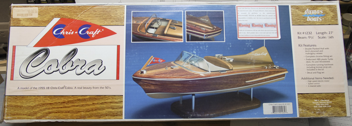
Back at the end of 2015, I was in Orlando, Florida, visiting Disney World (taking advantage of a perk of working for the mouse: free park entry!). One of the restaurants in Disney Springs (formerly Downtown Disney) was just FILLED with great looking large scale boat and ship models. I was inspired to take up a wooden model project again, except this time I wanted it to end up shiny. After a bit of research, I narrowed it down to a handful of possible kit options. Mostly I was looking at kits from Dumas, as they have some great looking Chris-Craft speedboat kits. I spent a Saturday morning making the rounds at my local hobby shops (living in the SF Bay Area, there are a few to choose from) and managed to find this kit:
With a length of 27 inches, it’s a fairly large scale project (at least for me and my limited building space).
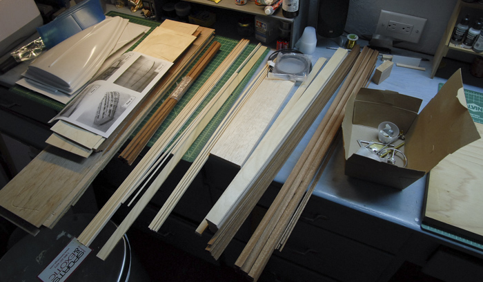
Like most kits of this type, it comes as a number of sheets of pre-cut parts, some strips of thin plywood, a bunch of strips of mahogany and bass wood, and some cast metal parts.
The instructions had me start by marking rib positions on a building board (spare plywood in this case) and then assembling and gluing the frame to the board.
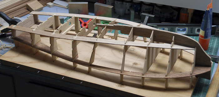
That was followed by adding a few stringers and the keel boards on the bottom of the boat.
Because of the rapid change in shape between the first rib and the nose of the boat, the front is shaped from balsa. The kit came with a sheet of half-inch-thick balsa that was cut into triangles and glued in place. Below you can see the rough blocks glued in place. I had to use a little bit of spare balsa that I had laying around in order to fill the space all of the way (those thin sheets right at the front).
Below you can see the rough shaping. This was done using first a jewelers saw to cut off big chunks of the wood, then a sanding drum on a Dremel for fast shaping and then finally some 150 grit sandpaper for finer shaping.
Next up was the under-planking. This consisted of 1/16 inch thick plywood strips that are laid diagonally on the bottom and sides of the hull. The instructions said to use a thick cyanoacrylate (super glue), but I found that when the strips needed to be bent a bit, the glue tended to not have the strength to hold the strips in place. I believe that this was mostly because there were fairly small areas in which the strips contacted the frame. I had actually started the planking and then found that I had started laying the planks going the wrong direction (dark spots in photo below was the glue that held them in place). When I discovered this, I tried to take those planks off and discovered that they came off so easily that I lost all confidence in the CA method.
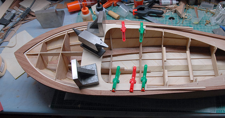
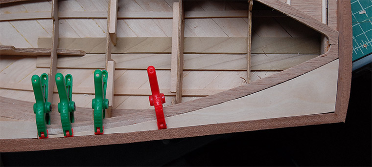
I decided instead to try good ol’ yellow carpenter’s glue. This required that the strips be clamped in place while the glue dried. Once dried, though, the glue was strong and the connection between the strips and frame was solid. I ended up going with this technique for all of the under-planking. Below you can see the transom in place as well as the first few planks.
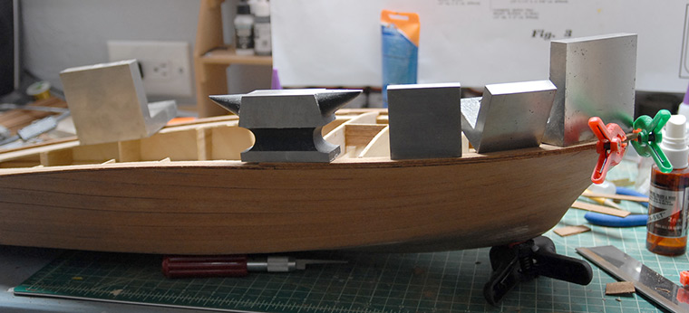
Below you can see some of the clamping and weighting I needed to do in order to hold planks in place while the glue dried. Those angle blocks weigh 3lbs each, and were providing a great deal of pressure on those planks.
A closer view of the same setup.
As I got closer and closer to the nose of the boat, the angle between the bottom planks and the chine (frame piece that is the line between the sides and bottom) became shallower and the area of contact between the two got smaller. What I decided to do was add a few strips of basswood, trimmed to the correct angle, in order to give more contact area. Below you can see those strips in place.
A different angle on the same strips. You can see that the left side is untrimmed, while the right side is trimmed to the angle of the strips of plywood.
Below you can see the entire bottom of the boat with under-planking on it. The top edge in this photo has been sanded even with the angle of the side, while the bottom edge still looks ragged because it has not yet been sanded smooth.
The planking of the sides was very similar. I did attempt to use straight sewing pins as temporary nails. This worked some times and other times just resulted in lots of bent pins and plenty of cursing.
Using thinner strips of plywood near the front. The thinner strips are easier to bend and can therefore be formed to the sharper curves near the bow.
With the under-planking complete, the whole hull got a first pass of sanding.
In a few places, a plank or two ended up lower than I would like. In the case below, I added another bit of strip on top and then sanded it flush to the surrounding planks.
After that first pass of sanding, I put a thin layer of wood filler over most of the hull. This filled in gaps, leveled out the surface and gave me something to sand down in order to get things nice and smooth before the top plank layer.
Below you can see the filled and sanded result, all ready for the mahogany plank layer.
That seems like a good place to stop for this post. The mahogany planking is nearly done, so look for that in a forthcoming blog post!
Thanks for reading!
With a length of 27 inches, it’s a fairly large scale project (at least for me and my limited building space).
Like most kits of this type, it comes as a number of sheets of pre-cut parts, some strips of thin plywood, a bunch of strips of mahogany and bass wood, and some cast metal parts.
The instructions had me start by marking rib positions on a building board (spare plywood in this case) and then assembling and gluing the frame to the board.
That was followed by adding a few stringers and the keel boards on the bottom of the boat.
Because of the rapid change in shape between the first rib and the nose of the boat, the front is shaped from balsa. The kit came with a sheet of half-inch-thick balsa that was cut into triangles and glued in place. Below you can see the rough blocks glued in place. I had to use a little bit of spare balsa that I had laying around in order to fill the space all of the way (those thin sheets right at the front).
Below you can see the rough shaping. This was done using first a jewelers saw to cut off big chunks of the wood, then a sanding drum on a Dremel for fast shaping and then finally some 150 grit sandpaper for finer shaping.
Next up was the under-planking. This consisted of 1/16 inch thick plywood strips that are laid diagonally on the bottom and sides of the hull. The instructions said to use a thick cyanoacrylate (super glue), but I found that when the strips needed to be bent a bit, the glue tended to not have the strength to hold the strips in place. I believe that this was mostly because there were fairly small areas in which the strips contacted the frame. I had actually started the planking and then found that I had started laying the planks going the wrong direction (dark spots in photo below was the glue that held them in place). When I discovered this, I tried to take those planks off and discovered that they came off so easily that I lost all confidence in the CA method.
I decided instead to try good ol’ yellow carpenter’s glue. This required that the strips be clamped in place while the glue dried. Once dried, though, the glue was strong and the connection between the strips and frame was solid. I ended up going with this technique for all of the under-planking. Below you can see the transom in place as well as the first few planks.
Below you can see some of the clamping and weighting I needed to do in order to hold planks in place while the glue dried. Those angle blocks weigh 3lbs each, and were providing a great deal of pressure on those planks.
A closer view of the same setup.
As I got closer and closer to the nose of the boat, the angle between the bottom planks and the chine (frame piece that is the line between the sides and bottom) became shallower and the area of contact between the two got smaller. What I decided to do was add a few strips of basswood, trimmed to the correct angle, in order to give more contact area. Below you can see those strips in place.
A different angle on the same strips. You can see that the left side is untrimmed, while the right side is trimmed to the angle of the strips of plywood.
Below you can see the entire bottom of the boat with under-planking on it. The top edge in this photo has been sanded even with the angle of the side, while the bottom edge still looks ragged because it has not yet been sanded smooth.
The planking of the sides was very similar. I did attempt to use straight sewing pins as temporary nails. This worked some times and other times just resulted in lots of bent pins and plenty of cursing.
Using thinner strips of plywood near the front. The thinner strips are easier to bend and can therefore be formed to the sharper curves near the bow.
With the under-planking complete, the whole hull got a first pass of sanding.
In a few places, a plank or two ended up lower than I would like. In the case below, I added another bit of strip on top and then sanded it flush to the surrounding planks.
After that first pass of sanding, I put a thin layer of wood filler over most of the hull. This filled in gaps, leveled out the surface and gave me something to sand down in order to get things nice and smooth before the top plank layer.
Below you can see the filled and sanded result, all ready for the mahogany plank layer.
That seems like a good place to stop for this post. The mahogany planking is nearly done, so look for that in a forthcoming blog post!
Thanks for reading!
Curtiss Jenny All Done!
14 - March - 2012 - 20:30
At long last, another model can be called done!
Since the last blog post, I've moved, gained a new (and improved!) model work space and managed to finish both the model and a simple base for it. Picking up where I last left off, I had a bit of carving to do to shape the propeller. It was constructed from a bunch of thin walnut strips, glued together to make a block that was thick enough to carve the prop from.
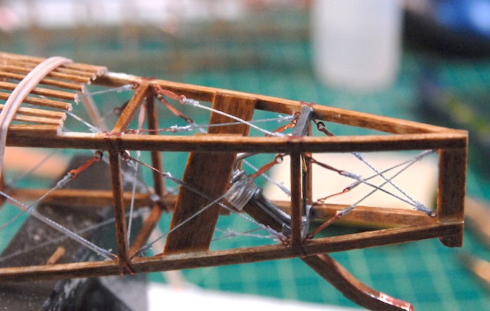
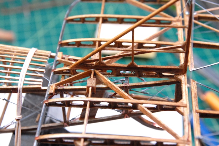
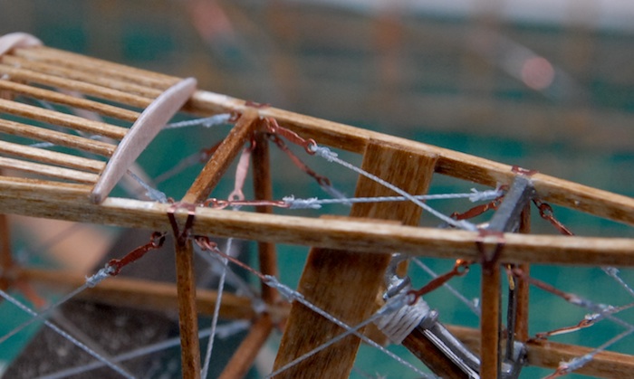
At the same time, I managed to start the wing rigging. There were a TON of wires on each side, which, on the real planes, kept the wings from folding up when flying.
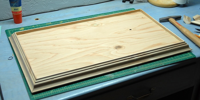
Once the wings were rigged up, there were a few extra wires to add on, the finished prop to attach and the plane was done! Next up was to put together a base of some sort to attach it to. I wanted some sort of base, so that I could fasten the model to it and thereby make it much easier to transport, less likely to damage and maybe add a bit of visual appeal. I headed to Home Depot and grabbed some plywood and wooden molding. Some quality time with a saw, and a few small nails, and I had myself the makings of a base. board.
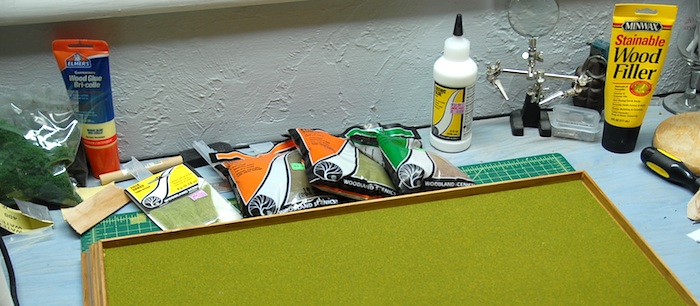
I decided that I wanted a simple covering for the base that was stain on the molding (that matched the plane) and a grass-like covering for the plywood. I grabbed some common model train terrain supplies and gave it a shot. This wasn't something that I had ever tried before, so I pretty much just winged it.
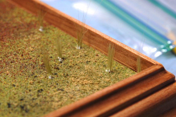
My shot at little tufts of grass:
 \
\
With that done, I was ready to photograph it. The challenge here was that this was pretty much the largest model I have ever made. I decided that instead of using my regular background, which is just a couple of large sheets of paper, I should instead order a proper roll of backdrop paper, which was 53 inches wide and way longer than I'll ever need. This presented me with the challenge of how to hang the roll up while shooting my photos without having to purchase a bunch of backdrop stands. After another trip to Home Depot, I came home with a broom handle and a length of light chain. A few hooks screwed into the broom handle (cut down by a few inches) and hooks into the overhead wood and I've got a removable paper roll hanger.
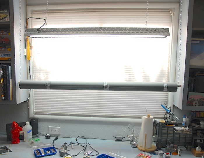
Then, I dragged out the photo equipment and spent an hour or two shooting photos.
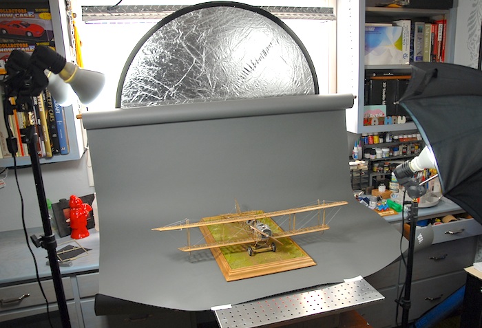
So, without further ado, here are the photos of the finished Model Airways Curtiss JN-4D Jenny:

Next up: A Machinen Krieger plastic model...
Since the last blog post, I've moved, gained a new (and improved!) model work space and managed to finish both the model and a simple base for it. Picking up where I last left off, I had a bit of carving to do to shape the propeller. It was constructed from a bunch of thin walnut strips, glued together to make a block that was thick enough to carve the prop from.
At the same time, I managed to start the wing rigging. There were a TON of wires on each side, which, on the real planes, kept the wings from folding up when flying.
Once the wings were rigged up, there were a few extra wires to add on, the finished prop to attach and the plane was done! Next up was to put together a base of some sort to attach it to. I wanted some sort of base, so that I could fasten the model to it and thereby make it much easier to transport, less likely to damage and maybe add a bit of visual appeal. I headed to Home Depot and grabbed some plywood and wooden molding. Some quality time with a saw, and a few small nails, and I had myself the makings of a base. board.
I decided that I wanted a simple covering for the base that was stain on the molding (that matched the plane) and a grass-like covering for the plywood. I grabbed some common model train terrain supplies and gave it a shot. This wasn't something that I had ever tried before, so I pretty much just winged it.
My shot at little tufts of grass:
\With that done, I was ready to photograph it. The challenge here was that this was pretty much the largest model I have ever made. I decided that instead of using my regular background, which is just a couple of large sheets of paper, I should instead order a proper roll of backdrop paper, which was 53 inches wide and way longer than I'll ever need. This presented me with the challenge of how to hang the roll up while shooting my photos without having to purchase a bunch of backdrop stands. After another trip to Home Depot, I came home with a broom handle and a length of light chain. A few hooks screwed into the broom handle (cut down by a few inches) and hooks into the overhead wood and I've got a removable paper roll hanger.
Then, I dragged out the photo equipment and spent an hour or two shooting photos.
So, without further ado, here are the photos of the finished Model Airways Curtiss JN-4D Jenny:
Next up: A Machinen Krieger plastic model...
Almost done...
14 - November - 2011 - 20:12
I'm finally seeing the light at the end of the tunnel on this project. All the big pieces are starting to go together and at the time of this writing all that is left is some rigging and the shaping of the propeller. I suppose I'll also have to fashion some sort of base for the plane to be attached to, in order to help keep it away from damage. Here's what's happened since the last post:
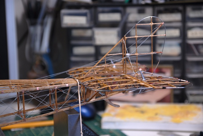
First up, the tail needed to be attached. When I went to fit the tail, I discovered that the turtleback ended a bit too far back on the fuselage, resulting in the tail hanging off the back. This made it so that the rudder wouldn't go on, and clearly, some adjustment would be needed. I brought out the razor saw and trimmed a few millimeters off of the turtle back.
This made some room for the tail to be fitted and the back edge of the vertical stabilizer lined up properly with the back of the fuselage.
Since I cut off the laser-cut part, I needed to craft a new rear rib for the turtle back. Fortunately I had kept the scrap thin plywood that the turtleback parts had come attached to. I snipped off a little bit of that wood, and fashioned a replacement rib. Here you can see it glued in place.
That new piece had to be stained to match the rest of the plane, and then a coat of polyurethane. Next, the tail was glued in place, the rudder attached and the various control lines rigged to connect to the cockpit fittings.
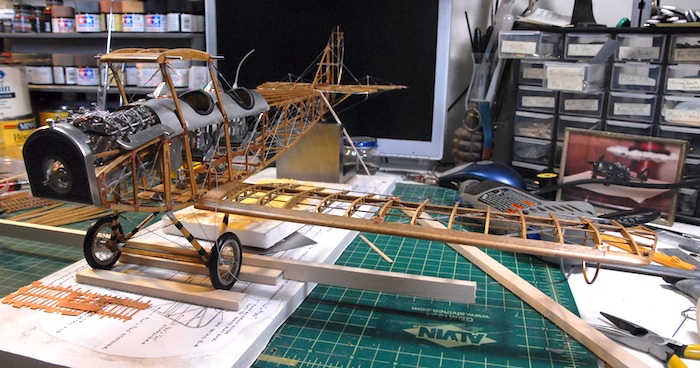
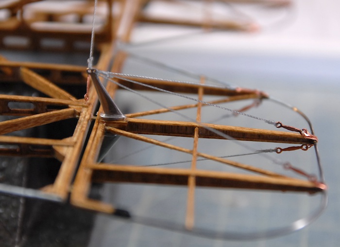
Next up were the lower wings. Below you can see the rough fitting. This mostly just consisted of me drilling out the holes for the connecting pins to go into and then setting the wing in place.
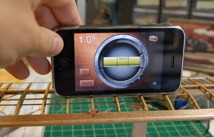
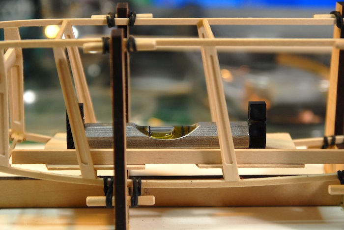
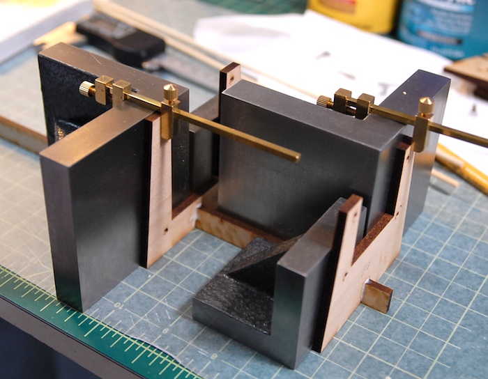
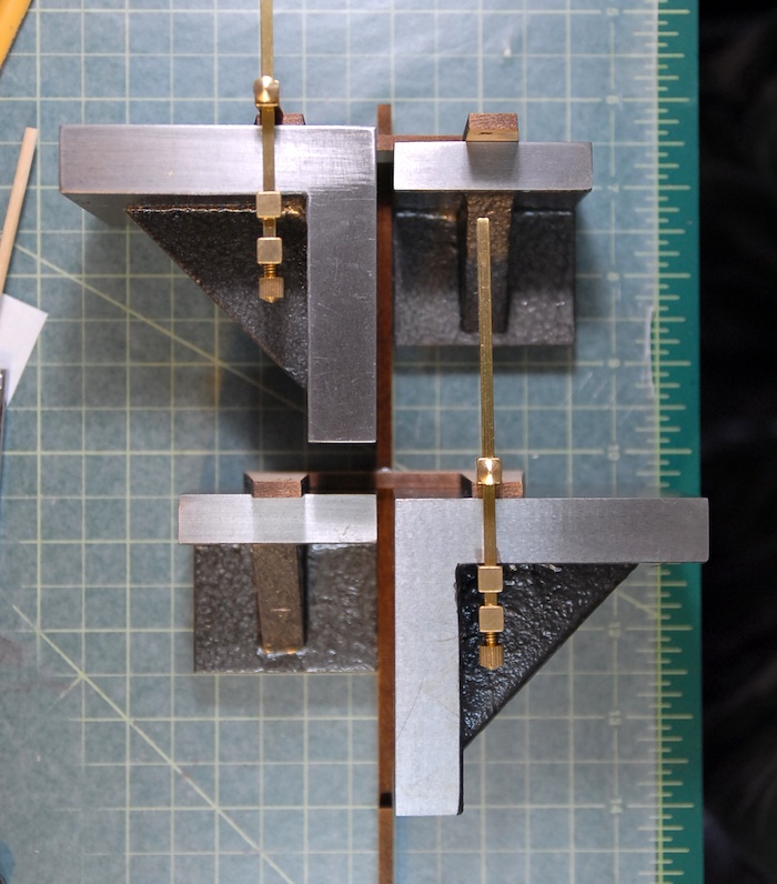
The lower wings are supposed to have one degree of dihedral. In order to get just such a thing, I had to build a little support rig which I could add little shims to until the wing was at just the right angle. Below you can see my high-tech angle measuring method along with my low-tech support and shim method.
Once the angle of the wings were set, a bit of epoxy held them in place permanently. Next, a similar fitting for the upper wings, although those just sit on top of the inter-plane struts, so were a bit easier to fit. They really just required a boring out of the connection holes, so that the wings could lay at the proper angles.
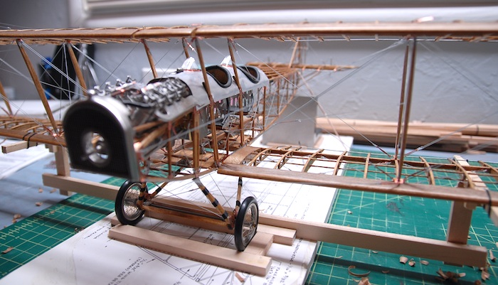
Finally, below you can see the state of the model this evening. The top wings are epoxied in place and the inter-plane struts are glued in place.
Next up: rigging and shaping of the propeller.
First up, the tail needed to be attached. When I went to fit the tail, I discovered that the turtleback ended a bit too far back on the fuselage, resulting in the tail hanging off the back. This made it so that the rudder wouldn't go on, and clearly, some adjustment would be needed. I brought out the razor saw and trimmed a few millimeters off of the turtle back.
This made some room for the tail to be fitted and the back edge of the vertical stabilizer lined up properly with the back of the fuselage.
Since I cut off the laser-cut part, I needed to craft a new rear rib for the turtle back. Fortunately I had kept the scrap thin plywood that the turtleback parts had come attached to. I snipped off a little bit of that wood, and fashioned a replacement rib. Here you can see it glued in place.
That new piece had to be stained to match the rest of the plane, and then a coat of polyurethane. Next, the tail was glued in place, the rudder attached and the various control lines rigged to connect to the cockpit fittings.
Next up were the lower wings. Below you can see the rough fitting. This mostly just consisted of me drilling out the holes for the connecting pins to go into and then setting the wing in place.
The lower wings are supposed to have one degree of dihedral. In order to get just such a thing, I had to build a little support rig which I could add little shims to until the wing was at just the right angle. Below you can see my high-tech angle measuring method along with my low-tech support and shim method.
Once the angle of the wings were set, a bit of epoxy held them in place permanently. Next, a similar fitting for the upper wings, although those just sit on top of the inter-plane struts, so were a bit easier to fit. They really just required a boring out of the connection holes, so that the wings could lay at the proper angles.
Finally, below you can see the state of the model this evening. The top wings are epoxied in place and the inter-plane struts are glued in place.
Next up: rigging and shaping of the propeller.
Engine Is In the Plane!
22 - August - 2011 - 21:24
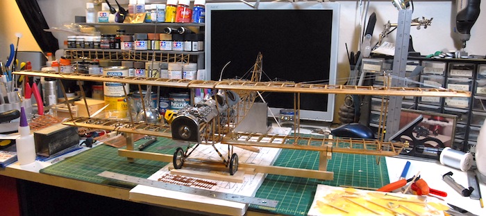
At long last, tonight I mounted the engine to the fuselage!
Here are a few images showing how I got there.
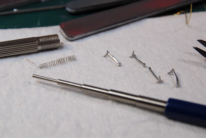
First, I made a few more 'springs' for the rockers and such.
That gave me the parts to finish up the cylinder assemblies.
Next up was the polishing and mounting of the exhaust headers.
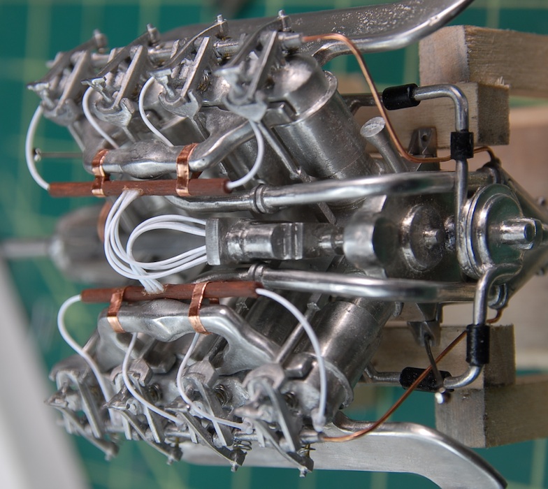
After that was a bit of wiring. This was tricky, as the instructions just mentioned gluing the wires to the spark plugs. Except that, in reality, the wire is very stiff and wouldn't stay glued to the plug tips. Anticipating this issue, I drilled tiny holes in the side of each plug and glued the wire tips into these holes. This was a bit of a pain, but seemed to work out decently. Next up were some little dowels, painted brown, to simulate the fiber tubes that collected and routed the plug wires on their way to the magneto. Finally, there were another eight wires that came out of the dowels and into the magneto.
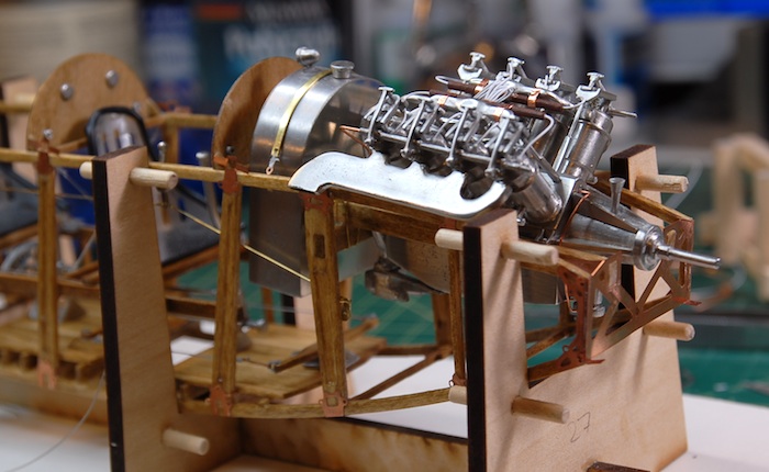
With that step complete, the next step was to mount the engine to the fuselage. While the engine isn't quite complete, all of the remaining steps require that the engine be in the plane, as they mostly involve various tubing and wiring.
Ta Da!
Next up: Wiring, tubes, the radiator and propeller.
Here are a few images showing how I got there.
First, I made a few more 'springs' for the rockers and such.
That gave me the parts to finish up the cylinder assemblies.
Next up was the polishing and mounting of the exhaust headers.
After that was a bit of wiring. This was tricky, as the instructions just mentioned gluing the wires to the spark plugs. Except that, in reality, the wire is very stiff and wouldn't stay glued to the plug tips. Anticipating this issue, I drilled tiny holes in the side of each plug and glued the wire tips into these holes. This was a bit of a pain, but seemed to work out decently. Next up were some little dowels, painted brown, to simulate the fiber tubes that collected and routed the plug wires on their way to the magneto. Finally, there were another eight wires that came out of the dowels and into the magneto.
With that step complete, the next step was to mount the engine to the fuselage. While the engine isn't quite complete, all of the remaining steps require that the engine be in the plane, as they mostly involve various tubing and wiring.
Ta Da!
Next up: Wiring, tubes, the radiator and propeller.
And Picking Back Up Again...
30 - October - 2011 - 20:45
I'm back!
I realize it has been a bit over two months since the last blog update, but I feel as though I have a decent excuse. It turns out that I went and got married about a month ago. So, what with various wedding preparations, the wedding itself and then the honeymoon afterwards, I hardly had any spare moments for working on the ol model. But now that that is all settled and I've got some free time back again, I have finally got a bit of an update.
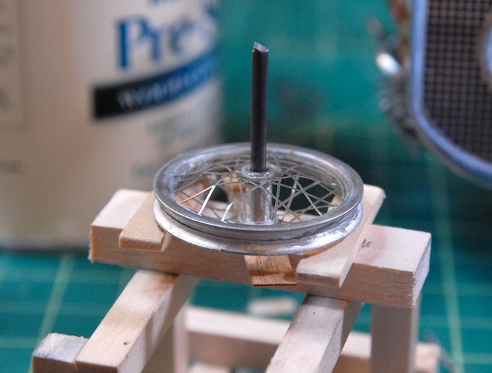
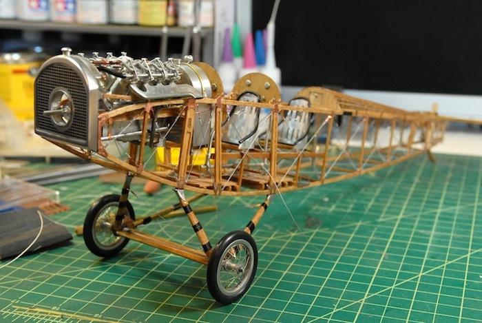
I'm getting into the home stretch now, and the model is beginning to wrap up. I've assembled the wheels, which were a combination of cast hubs and rims and photo-etch spokes. It seems like these sorts of things never fit quite right, and so each wheel has one side that is a little more warped than I would prefer, since the spoke discs were just a hair bigger than they should be. Someone with more patience and some fore knowledge of this might file them all the way around to be just a little smaller, but I'm not and I didn't, so I just bent them into place and called it good.
Below you can see the wheel, and also the little jig that I made from the engine stand and a leftover part of the axle. This setup put the rim and the hub at just the right offset to keep everything centered nicely.
While that was going on, I also was working on putting the gear assembly together. It was a fairly simple setup, with the same fitting of metal parts to wood that was required on the interwing struts that I put together earlier in the build, but haven't fitted to the plane yet. With a bit of sanding and shaping, the various wooden parts were contoured and smoothed. Since this gear was going to have to support the weight of the model, which, with the engine in there, is not insubstantial, I decided to do a little reinforcing of the joints. I drilled a few holes through the joint/hub part (where everything connects) and put some metal rods through that and into each other piece of wood. Hopefully this will add enough strength to keep everything happy attached.
With some O-rings stretched around the wheels for tires and some string wrapped around the landing gear, the plane is finally standing on it's own legs! On a side note, there is a tail skid that Ive finished as well, but I don't have any photos of that handy, so look for that next time.
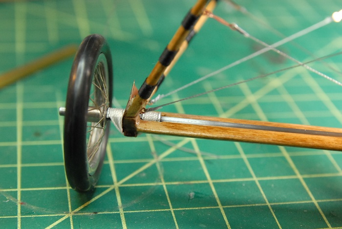
Here is a close up of the wrapped string. On the full-size plane, this added reinforcement to the wood, perhaps keeping it from splitting on landing. On the model, it is just nylon string glued in place with a dab of superglue.
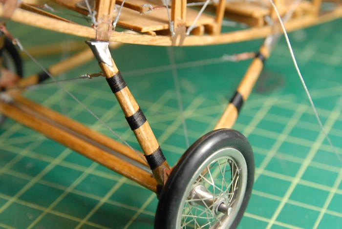
To simulate the simple bungie-cord-like suspension that the plane had, the model has a couple of metal fittings and some wrapped white string. This is actually holding the axle in place, though, so I had to be sure it was good and tight. Once in place, a dab of superglue made sure it wasn't going to go anywhere.
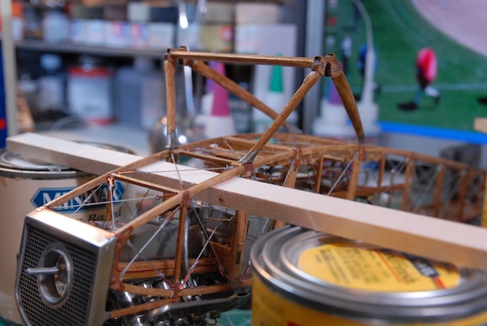
Finally, bringing the blog up to what I was working on just a few hours ago, the aluminum cowl around the cockpit in in progress. Below you can see it bend into place. I used the plank-soaking tube that I made for the Armed Virginia Sloop model (out of some simple PVC pipe) as a form to bend the metal over. The metal just gets bent a bit and then glued into place with the help of a few tabs that wrap under the wooden longerons.
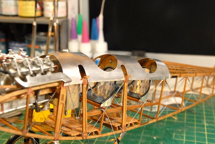
Next up: windshields, cowling trim, and beginning to put all of the parts together!
I realize it has been a bit over two months since the last blog update, but I feel as though I have a decent excuse. It turns out that I went and got married about a month ago. So, what with various wedding preparations, the wedding itself and then the honeymoon afterwards, I hardly had any spare moments for working on the ol model. But now that that is all settled and I've got some free time back again, I have finally got a bit of an update.
I'm getting into the home stretch now, and the model is beginning to wrap up. I've assembled the wheels, which were a combination of cast hubs and rims and photo-etch spokes. It seems like these sorts of things never fit quite right, and so each wheel has one side that is a little more warped than I would prefer, since the spoke discs were just a hair bigger than they should be. Someone with more patience and some fore knowledge of this might file them all the way around to be just a little smaller, but I'm not and I didn't, so I just bent them into place and called it good.
Below you can see the wheel, and also the little jig that I made from the engine stand and a leftover part of the axle. This setup put the rim and the hub at just the right offset to keep everything centered nicely.
While that was going on, I also was working on putting the gear assembly together. It was a fairly simple setup, with the same fitting of metal parts to wood that was required on the interwing struts that I put together earlier in the build, but haven't fitted to the plane yet. With a bit of sanding and shaping, the various wooden parts were contoured and smoothed. Since this gear was going to have to support the weight of the model, which, with the engine in there, is not insubstantial, I decided to do a little reinforcing of the joints. I drilled a few holes through the joint/hub part (where everything connects) and put some metal rods through that and into each other piece of wood. Hopefully this will add enough strength to keep everything happy attached.
With some O-rings stretched around the wheels for tires and some string wrapped around the landing gear, the plane is finally standing on it's own legs! On a side note, there is a tail skid that Ive finished as well, but I don't have any photos of that handy, so look for that next time.
Here is a close up of the wrapped string. On the full-size plane, this added reinforcement to the wood, perhaps keeping it from splitting on landing. On the model, it is just nylon string glued in place with a dab of superglue.
To simulate the simple bungie-cord-like suspension that the plane had, the model has a couple of metal fittings and some wrapped white string. This is actually holding the axle in place, though, so I had to be sure it was good and tight. Once in place, a dab of superglue made sure it wasn't going to go anywhere.
Finally, bringing the blog up to what I was working on just a few hours ago, the aluminum cowl around the cockpit in in progress. Below you can see it bend into place. I used the plank-soaking tube that I made for the Armed Virginia Sloop model (out of some simple PVC pipe) as a form to bend the metal over. The metal just gets bent a bit and then glued into place with the help of a few tabs that wrap under the wooden longerons.
Next up: windshields, cowling trim, and beginning to put all of the parts together!
Engine Updates
07 - August - 2011 - 20:19
As some may have noticed, it has been quite a while since my last update. Those same some might be thinking, "Oh, it just another blog, where the updates get further and further apart." I would like to rebut that with, "Balderdash! The updates have been sparse recently because I am in the midst of wedding planning and have had very little time for modeling, let alone model blogging!"
With that said, I got a bit of time this weekend to do a little bit of modeling, and got the model desk reassembled (the web cam part had been taken apart for wedding related reasons). Once things were back in order, cleaned up and ready to roll, I managed to test out an idea I had been toying around with for some upgrades to the engine, and I think they turned out pretty well. But first, let's get up to date with the state of the model.
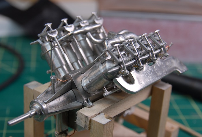
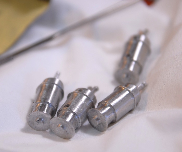
When last I wrote about it, the engine was just beginning assembly, with the large pieces coming together. The next step in the process was to add the cylinders. Here are a few of them, sanded and polished and ready to be epoxied to the engine block.
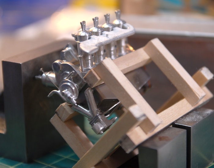
In order to get them all properly aligned (there is a bit of slop in the attachment points on the engine block), the directions recommended using the intake runner and exhaust headers to insure that everything will align later on. In order to make this easier, I set the whole engine assembly up so that the cylinders balanced on the top while the epoxy set.
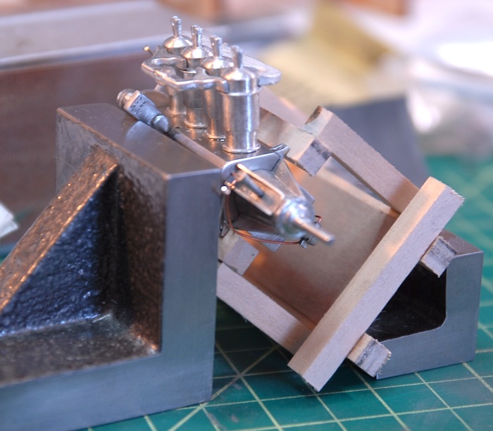
And then the other side:
After the cylinders were all in place, I added on the water inlet piping and the air intakes.
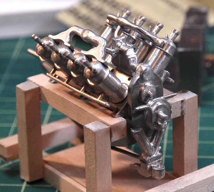
Along with those, there were other miscellaneous pipes that got added. Below you can see the test-fit of the intermediate piping. The kit came with some clear rubber tubing for these parts, but since rubber tubing is a pain to paint, AND I already had various sizes of styrene tubing, I decided to go with the hard styrene tubes, cut to length.
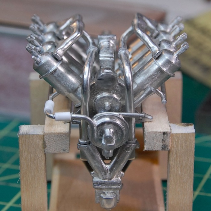
That tubing was then painted black and glued in place on both sides.
This brings me to the previously-mentioned upgrade. The kit has various pushrods, rockers and such for the top of each cylinder. Cast into two of those parts are 'springs' that I felt were not satisfactory. The castings were shallow and hardly looked like springs at all. So, I decided that I could replace the springs with a center rod and some wound wire that looks like a spring. I wound some very thin wire that I had left from a previous kit around a mandrel tool, and cut some lengths of thicker brass wire for the centers. I cut off the cast springs, filed everything clean and drilled some tiny holes to keep the center rods in place.
Here are the results on my first test cylinder:
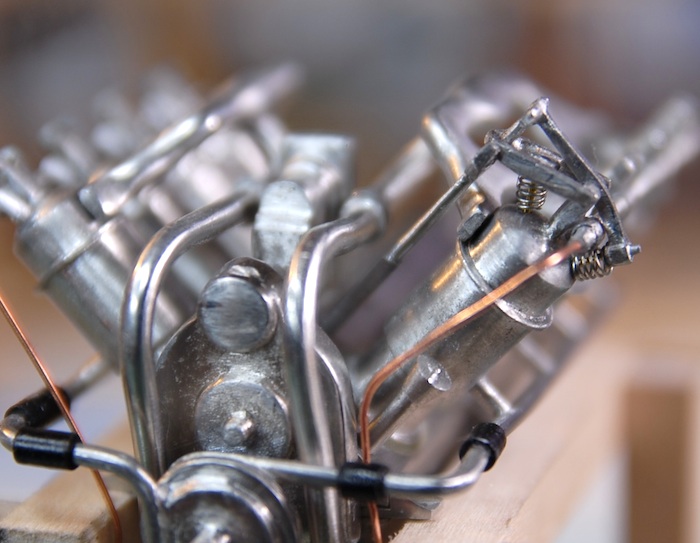
I think these look much more like the real engine. I've got a pile of photo reference of the engine that I have collected and have found it very useful to refer to while building.
And that brings us up to the present. I've got two of the eight cylinders done with the springs, as of tonight, and hopefully I can continue with this during the week and next weekend.The next update should see the engine mounted on the fuselage! Stay tuned!
With that said, I got a bit of time this weekend to do a little bit of modeling, and got the model desk reassembled (the web cam part had been taken apart for wedding related reasons). Once things were back in order, cleaned up and ready to roll, I managed to test out an idea I had been toying around with for some upgrades to the engine, and I think they turned out pretty well. But first, let's get up to date with the state of the model.
When last I wrote about it, the engine was just beginning assembly, with the large pieces coming together. The next step in the process was to add the cylinders. Here are a few of them, sanded and polished and ready to be epoxied to the engine block.
In order to get them all properly aligned (there is a bit of slop in the attachment points on the engine block), the directions recommended using the intake runner and exhaust headers to insure that everything will align later on. In order to make this easier, I set the whole engine assembly up so that the cylinders balanced on the top while the epoxy set.
And then the other side:
After the cylinders were all in place, I added on the water inlet piping and the air intakes.
Along with those, there were other miscellaneous pipes that got added. Below you can see the test-fit of the intermediate piping. The kit came with some clear rubber tubing for these parts, but since rubber tubing is a pain to paint, AND I already had various sizes of styrene tubing, I decided to go with the hard styrene tubes, cut to length.
That tubing was then painted black and glued in place on both sides.
This brings me to the previously-mentioned upgrade. The kit has various pushrods, rockers and such for the top of each cylinder. Cast into two of those parts are 'springs' that I felt were not satisfactory. The castings were shallow and hardly looked like springs at all. So, I decided that I could replace the springs with a center rod and some wound wire that looks like a spring. I wound some very thin wire that I had left from a previous kit around a mandrel tool, and cut some lengths of thicker brass wire for the centers. I cut off the cast springs, filed everything clean and drilled some tiny holes to keep the center rods in place.
Here are the results on my first test cylinder:
I think these look much more like the real engine. I've got a pile of photo reference of the engine that I have collected and have found it very useful to refer to while building.
And that brings us up to the present. I've got two of the eight cylinders done with the springs, as of tonight, and hopefully I can continue with this during the week and next weekend.The next update should see the engine mounted on the fuselage! Stay tuned!
Engine and Deskcam
26 - June - 2011 - 20:49
The Engine!
So, I've finally arrived at the reason that I purchased this kit in the first place: the engine. I was completely taken by the engine detail in the product images and wanted a shot at making that same engine and perhaps even improving upon it. The engine, fuel tank and radiator are all mostly made up of cast Britannia metal, which is a mixture of tin, antimony and copper. These parts are all delivered in the kit as raw castings, which gives them a dull surface and sometimes rough details.
Some of the raw engine block castings:
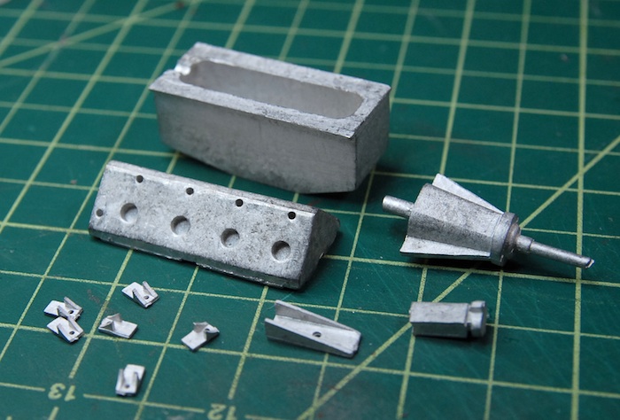
This means that the bulk of the work on the engine is the cleanup, sanding and polishing of these parts, in order to bring them up to a quality finish that complements the rest of the kit. I'm currently wearing through various sanding sticks and a few bits of sandpaper, but I've got some higher grit sandpaper arriving tomorrow, which should make short work of getting these parts in order.
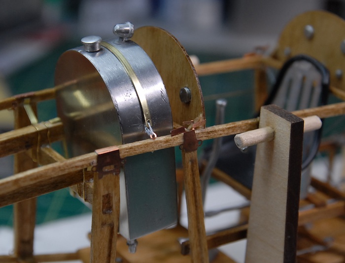
First item to be added was the fuel tank, which was actually a combination of a cast metal frame and photo-etch front and back plates. Here you can see some pictures of the final product after quite a bit of sanding, polishing and a bit of buffing with the ol Dremel. Added to that are three other separately-cast parts, the fuel cap and fuel gauge on the top and sediment trap hanging off of the bottom. This tank is held in place by three brass strips, two cradling it underneath and one over the top.
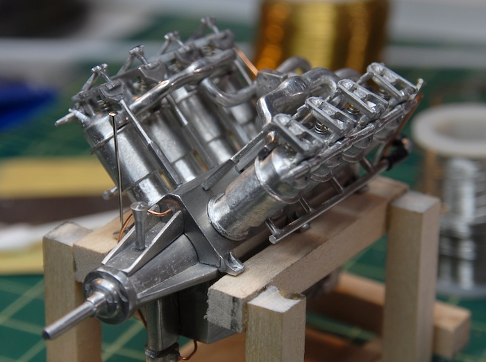
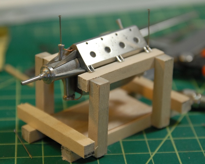
Next up was the engine block itself. For a little while I was working with the block, unattached from the fuselage, but once I started adding more parts, this seemed less and less practical. So, I took a bit of scrap wood and built a little engine stand for it. Here you can see the engine cleaned up a bit and mounted on the temporary stand.
Stay tuned for more additions to the engine as work continues!
Desk Cam Gets a New Computer and Comes Back to Life!
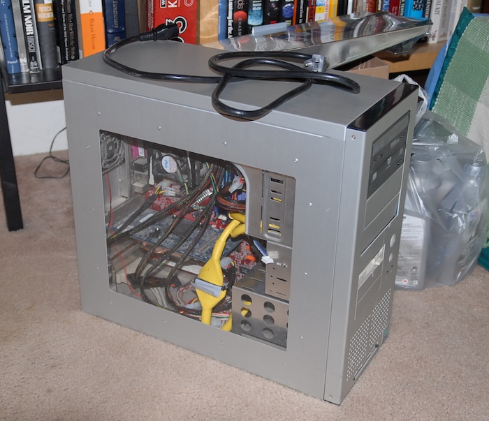
As, I'm sure, many of you noticed (or perhaps didn't notice), the computer that runs my model desk web cam and time-lapse camera managed to die a couple of weeks ago. I think the culprit was the local power company replacing a nearby transformer combined with the computer power supply being on its last legs. Whatever the cause, when the power supply failed it took the motherboard with it, so now all the computer is good for (after I replaced the fried power supply) is moving a bit of air around. Yup, the only things that seem to still work are all of the fans. Alas, poor computer, I knew it well.
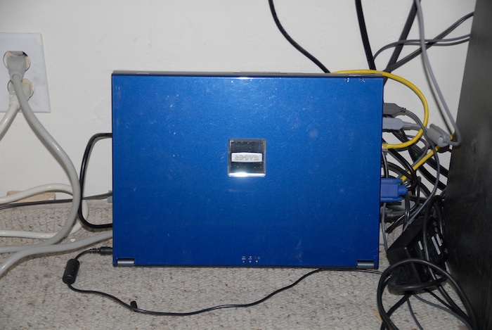
As the untimely demise of my model desk computer left me without a way to run my time-lapse camera and no way to update my desk cam web page, I had to find a new way to run things. Fortunately, I still had my old laptop computer in a closet (actually, the original desk-cam computer ALSO came back to life out of a closet), which I thought might be able to be used in a pinch. So, today I dragged it out, plugged it into all of the appropriate cables, updated and installed various bits of software, and now have a whole new computer running under my model desk!
Rest in Pieces, old model desk computer.
:(
Long live the new model desk computer!
The upside here, is that I've gained a great deal more leg room under the model desk and probably will save a little bit of electricity. Here's the current state of the model desk, including new computer and such:
That's all for now. Tune in next time for more engine progress and hopefully no further news about the model desk computer ;)
So, I've finally arrived at the reason that I purchased this kit in the first place: the engine. I was completely taken by the engine detail in the product images and wanted a shot at making that same engine and perhaps even improving upon it. The engine, fuel tank and radiator are all mostly made up of cast Britannia metal, which is a mixture of tin, antimony and copper. These parts are all delivered in the kit as raw castings, which gives them a dull surface and sometimes rough details.
Some of the raw engine block castings:
This means that the bulk of the work on the engine is the cleanup, sanding and polishing of these parts, in order to bring them up to a quality finish that complements the rest of the kit. I'm currently wearing through various sanding sticks and a few bits of sandpaper, but I've got some higher grit sandpaper arriving tomorrow, which should make short work of getting these parts in order.
First item to be added was the fuel tank, which was actually a combination of a cast metal frame and photo-etch front and back plates. Here you can see some pictures of the final product after quite a bit of sanding, polishing and a bit of buffing with the ol Dremel. Added to that are three other separately-cast parts, the fuel cap and fuel gauge on the top and sediment trap hanging off of the bottom. This tank is held in place by three brass strips, two cradling it underneath and one over the top.
Next up was the engine block itself. For a little while I was working with the block, unattached from the fuselage, but once I started adding more parts, this seemed less and less practical. So, I took a bit of scrap wood and built a little engine stand for it. Here you can see the engine cleaned up a bit and mounted on the temporary stand.
Stay tuned for more additions to the engine as work continues!
Desk Cam Gets a New Computer and Comes Back to Life!
As, I'm sure, many of you noticed (or perhaps didn't notice), the computer that runs my model desk web cam and time-lapse camera managed to die a couple of weeks ago. I think the culprit was the local power company replacing a nearby transformer combined with the computer power supply being on its last legs. Whatever the cause, when the power supply failed it took the motherboard with it, so now all the computer is good for (after I replaced the fried power supply) is moving a bit of air around. Yup, the only things that seem to still work are all of the fans. Alas, poor computer, I knew it well.
As the untimely demise of my model desk computer left me without a way to run my time-lapse camera and no way to update my desk cam web page, I had to find a new way to run things. Fortunately, I still had my old laptop computer in a closet (actually, the original desk-cam computer ALSO came back to life out of a closet), which I thought might be able to be used in a pinch. So, today I dragged it out, plugged it into all of the appropriate cables, updated and installed various bits of software, and now have a whole new computer running under my model desk!
Rest in Pieces, old model desk computer.
:(
Long live the new model desk computer!
The upside here, is that I've gained a great deal more leg room under the model desk and probably will save a little bit of electricity. Here's the current state of the model desk, including new computer and such:
That's all for now. Tune in next time for more engine progress and hopefully no further news about the model desk computer ;)
Cockpit Fittings
19 - June - 2011 - 21:45
Picking up from the last post, the rigging for the fuselage is complete between the tail and the cockpit. I've left off around the cockpit so that it is easier to add various fittings, seats, etc.
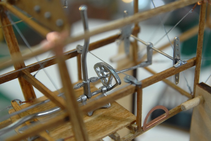
First up in the fittings were the rudder pedals and their connections and mounting points.
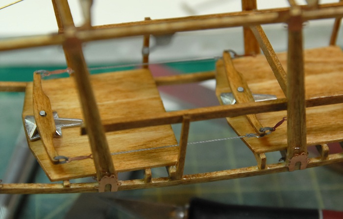
Those were followed by the control sticks and their various connections.
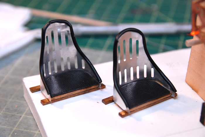
Next up were the seats. The kit came with photo-etch metal backs and wooden seats. The instructions mentioned that the real seats were covered with cloth on the backs and had pads on the seats. I decided that I should add a few of those extras to the seats on my plane. I had some tubing left over from a previous model that I used to line the edges of the seat backs. I feel that this had mixed results and I am not entirely happy with the results. For the cushions, I decided that I would find some leather-like fabric and wrap that around some wood.
I went to my local hobby shop in search of such a material, but they didn't have anything like that for purchase. But I DID notice a dollhouse chair there, for about $8, that had the type of material that I was looking for. So, I decided that instead of going store to store, looking for what I wanted, I would just buy the chair and strip the cloth off of it.
Behold, the sacrificial chair:
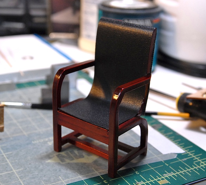
And the end result of my chair-enhancing efforts:
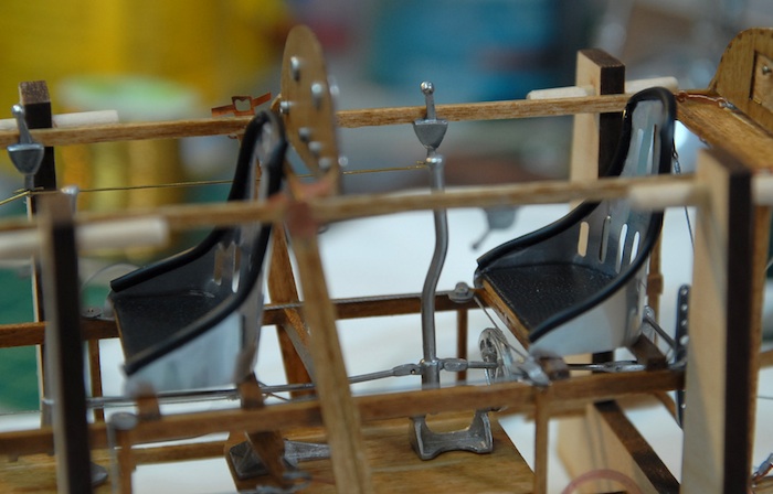
Before installing the chairs into the cockpits, I had to do just a bit of rigging. Here you can see the aileron control wires.
And finally, the seats installed.
With this done, I'm moving on to the engine and fuel tank. It's a fun-filled world of cast metal and sanding/polishing. Stay tuned for further adventures!
First up in the fittings were the rudder pedals and their connections and mounting points.
Those were followed by the control sticks and their various connections.
Next up were the seats. The kit came with photo-etch metal backs and wooden seats. The instructions mentioned that the real seats were covered with cloth on the backs and had pads on the seats. I decided that I should add a few of those extras to the seats on my plane. I had some tubing left over from a previous model that I used to line the edges of the seat backs. I feel that this had mixed results and I am not entirely happy with the results. For the cushions, I decided that I would find some leather-like fabric and wrap that around some wood.
I went to my local hobby shop in search of such a material, but they didn't have anything like that for purchase. But I DID notice a dollhouse chair there, for about $8, that had the type of material that I was looking for. So, I decided that instead of going store to store, looking for what I wanted, I would just buy the chair and strip the cloth off of it.
Behold, the sacrificial chair:
And the end result of my chair-enhancing efforts:
Before installing the chairs into the cockpits, I had to do just a bit of rigging. Here you can see the aileron control wires.
And finally, the seats installed.
With this done, I'm moving on to the engine and fuel tank. It's a fun-filled world of cast metal and sanding/polishing. Stay tuned for further adventures!
Strings and Things
30 - May - 2011 - 16:28
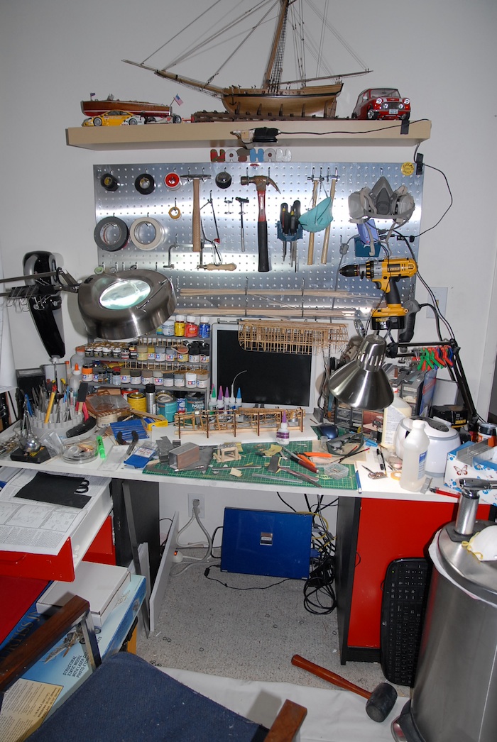
At the end of the last update, I had assembled most of the wooden components of the fuselage. Since then, almost all of the rest of the wooden parts have been attached, the whole thing has been stained, and I've added a few coats of polyurethane. I'm now on to an intermediate step of adding many of the rigging strings to the back half of the fuselage before starting to add the various controls and engine parts to the front half.
With that in mind, here are some photos of what I've been up to, along with brief explanations.
Below is an image of the turtleback all assembled. It turns out that it would have probably been a better idea to assemble this off of the main fuselage, and then add it later, as it ended up making some of the rigging a bit harder.
Here is the whole fuselage right after having the turtleback attached and right before staining.
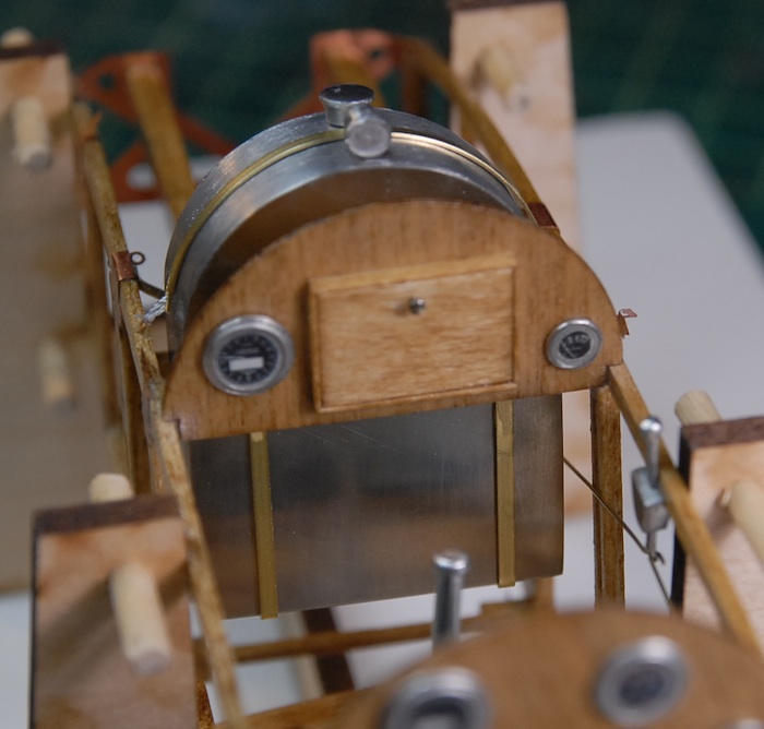
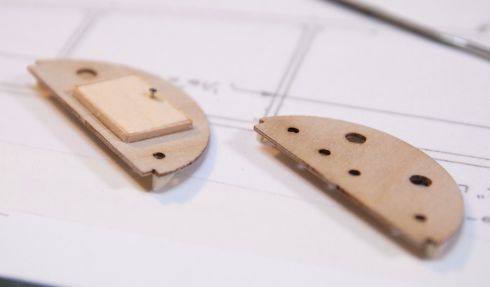
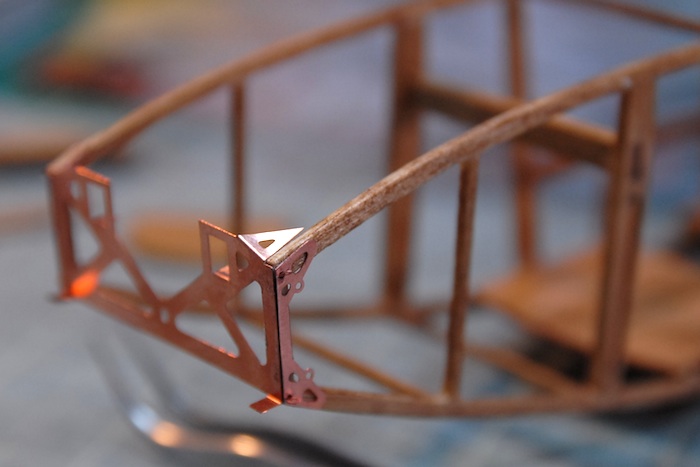
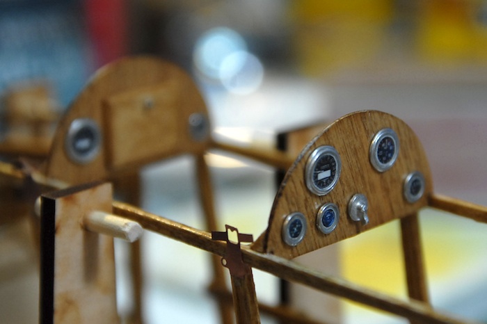
Here are the two control panels. The front one (for the navigator) has a little scratch-built map case. Although it's a little blurry in this image, the knob for the map case door is made from a pin head. I've left the dials and such off, as I wanted to stain and polyurethane the parts first.
Here is the fuselage right after staining.
Once the stain and polyurethane were on there, I could start gluing on some of the photo-etch metal parts. Here is a close-up of the frame that goes in front of the engine.
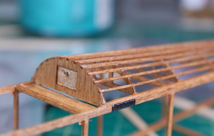
Here is a close-up of the little door that is at the front end of the turtleback.
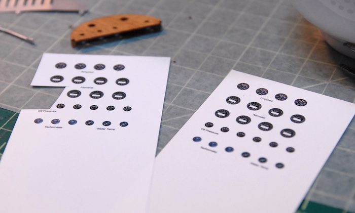
Next up was something new to me: printing my own decals. The kit doesn't provide any sort of instrumentation graphics, but rather only comes with the cast metal base parts. I thought this might be a good excuse to try my hand at making decals. I picked up a package of ink-jet-printer decal sheets and a can of decal sealer at my local hobby shop and then spent a few hours scouring the internet for images of old airplane gauges. With some cleanup work in Photoshop, and a bit of experimentation with the printer, I was able to print myself a few sheets of gauges. The sheets below have so many because I wasn't sure how tough the decals would be, and fully expected to ruin a few before getting one to transfer correctly. I also printed one set on a clear sheet and one on a white sheet. It turned out that the decals held up great and the white-backed ones looked good, so I have lots of extra gauges now.
Here you can see a few of the gauge decals in place. Once all was said and done, I think they ended up a bit smaller than I would like, but I had erred on the small side to be sure that they would fit in the tiny embossed ring of the cast metal part.
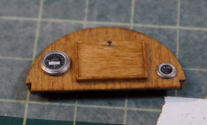
Here are the two completed control panels in place and with all decals applied.
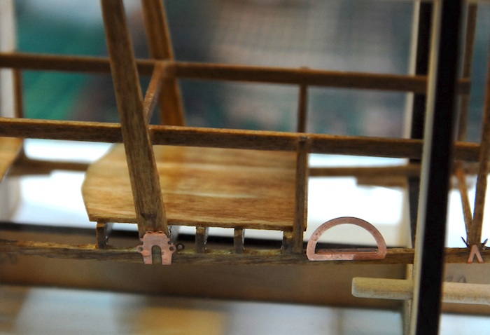
A few more photo-etched parts in place. The half-circle one is where the pilots step is, used to step up into the plane.
The engine-bearing supports, with various straps, wires, etc, holding them in place.
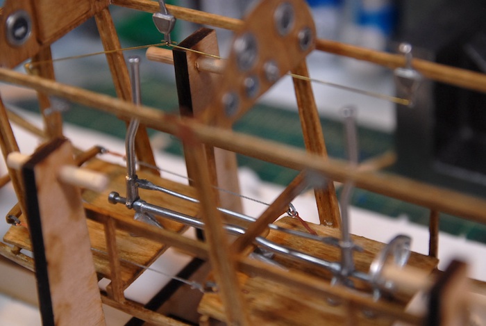
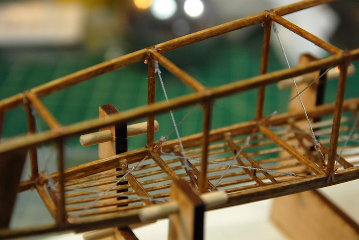
Finally, a sneak preview of the (in progress) next fun-filled step: Rigging the fuselage.
Thanks for tuning in! Hopefully next update will see the fuselage complete and work on the engine beginning.
With that in mind, here are some photos of what I've been up to, along with brief explanations.
Below is an image of the turtleback all assembled. It turns out that it would have probably been a better idea to assemble this off of the main fuselage, and then add it later, as it ended up making some of the rigging a bit harder.
Here is the whole fuselage right after having the turtleback attached and right before staining.
Here are the two control panels. The front one (for the navigator) has a little scratch-built map case. Although it's a little blurry in this image, the knob for the map case door is made from a pin head. I've left the dials and such off, as I wanted to stain and polyurethane the parts first.
Here is the fuselage right after staining.
Once the stain and polyurethane were on there, I could start gluing on some of the photo-etch metal parts. Here is a close-up of the frame that goes in front of the engine.
Here is a close-up of the little door that is at the front end of the turtleback.
Next up was something new to me: printing my own decals. The kit doesn't provide any sort of instrumentation graphics, but rather only comes with the cast metal base parts. I thought this might be a good excuse to try my hand at making decals. I picked up a package of ink-jet-printer decal sheets and a can of decal sealer at my local hobby shop and then spent a few hours scouring the internet for images of old airplane gauges. With some cleanup work in Photoshop, and a bit of experimentation with the printer, I was able to print myself a few sheets of gauges. The sheets below have so many because I wasn't sure how tough the decals would be, and fully expected to ruin a few before getting one to transfer correctly. I also printed one set on a clear sheet and one on a white sheet. It turned out that the decals held up great and the white-backed ones looked good, so I have lots of extra gauges now.
Here you can see a few of the gauge decals in place. Once all was said and done, I think they ended up a bit smaller than I would like, but I had erred on the small side to be sure that they would fit in the tiny embossed ring of the cast metal part.
Here are the two completed control panels in place and with all decals applied.
A few more photo-etched parts in place. The half-circle one is where the pilots step is, used to step up into the plane.
The engine-bearing supports, with various straps, wires, etc, holding them in place.
Finally, a sneak preview of the (in progress) next fun-filled step: Rigging the fuselage.
Thanks for tuning in! Hopefully next update will see the fuselage complete and work on the engine beginning.
Fuselage Continues
09 - May - 2011 - 20:27
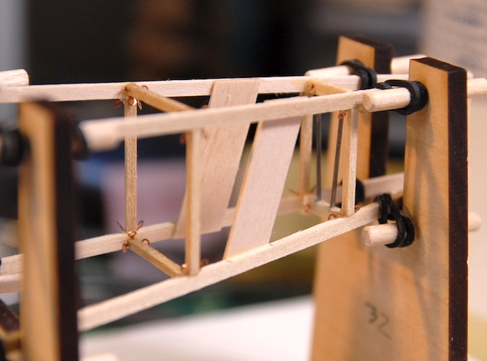
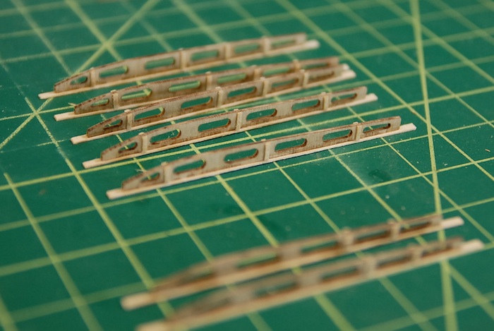
In the last post, I mentioned that I was not happy with the construction method used in the kit instructions to make the mortised fuselage ribs. The instructions wanted the ribs to be cut from a solid piece and the mortises carved out from those. I made one test piece and found that: a) this is really hard b) the wood that the kit came with for these parts was not the best quality, and tended to flake apart during the carving and c) the final product, because of a and b, was simply not as refined and clean as I would like.
So, what I ended up doing was to get three strips of wood, cut the mortise shape out of two of them, and then sandwich them all together to create a much better looking part. Below you can see what I ended up with, as it is being glued to one half of the fuselage.
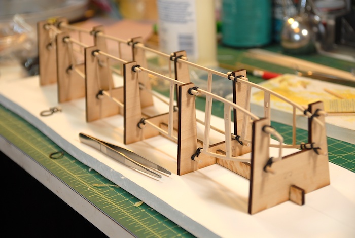
Once I got those parts all made, putting together the two sides of the fuselage went pretty quickly. Below you can see the two sides attached to the fuselage building jig, which holds everything straight and square while the cross pieces are glued in.
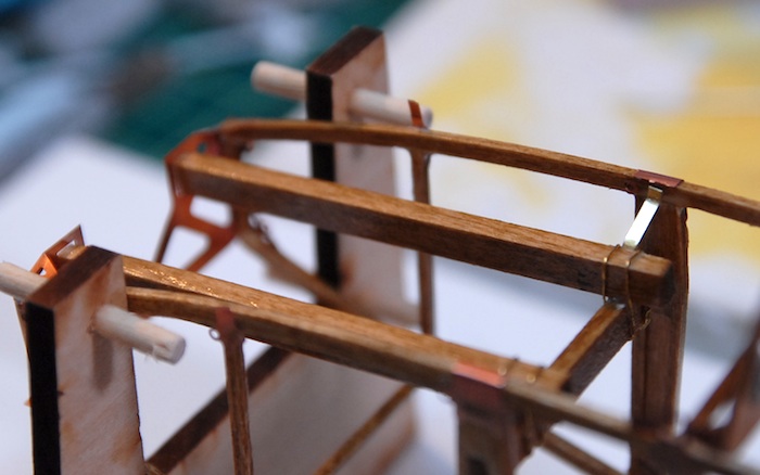
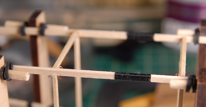
On the real plane, the top longerons (supposedly a real word) are spliced together behind the cockpit. I'm assuming this is because either a piece of wood that long was tricky to find, or perhaps the front of the plane needed wood of a different type that the tail did. Either way, my whole plane is made of basswood, and it's actually pretty easy to find a 16" long strip of wood, so I don't have to put in a real splice. Instead, the instructions had me wrap a section in thin nylon cord, to give the look of a spliced section.
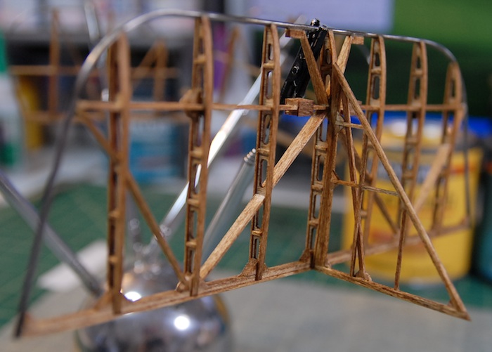
At the tail of the fuselage, there are a number of additions that are meant to strengthen the structure around the tail skid. For my purposes, this just meant a couple thick strips on the sides and a few steel wires in between the top and bottom.
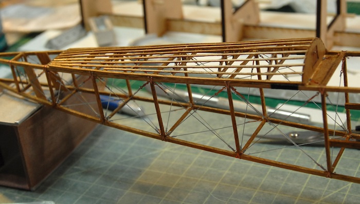
It was at this point that I found that I am going to need to start skipping sections of the instructions in order to facilitate the stain and polyurethane that I am putting on the model. I need to get as much of the wooden parts together, skip the addition of various metal parts, and still try to leave it all open enough that adding the metal parts later is easy. So, at this point I've skipped adding some of the engine mounting hardware because of the large photo-etch parts that that would require and have, instead, moved on to installing the cockpit flooring. Below you can see my efforts to get the two floors relatively level before fitting all the support beams underneath them.
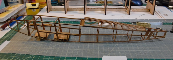
Finally, here is the fuselage out of the building jig, and with the floor support beams in place. There is still lots of work to be done on the fuselage, but actually only a few more steps before I stain the whole thing and apply the polyurethane.
That's all I've got for now. Stay tuned for more action-packed model-building chronicles!!
So, what I ended up doing was to get three strips of wood, cut the mortise shape out of two of them, and then sandwich them all together to create a much better looking part. Below you can see what I ended up with, as it is being glued to one half of the fuselage.
Once I got those parts all made, putting together the two sides of the fuselage went pretty quickly. Below you can see the two sides attached to the fuselage building jig, which holds everything straight and square while the cross pieces are glued in.
On the real plane, the top longerons (supposedly a real word) are spliced together behind the cockpit. I'm assuming this is because either a piece of wood that long was tricky to find, or perhaps the front of the plane needed wood of a different type that the tail did. Either way, my whole plane is made of basswood, and it's actually pretty easy to find a 16" long strip of wood, so I don't have to put in a real splice. Instead, the instructions had me wrap a section in thin nylon cord, to give the look of a spliced section.
At the tail of the fuselage, there are a number of additions that are meant to strengthen the structure around the tail skid. For my purposes, this just meant a couple thick strips on the sides and a few steel wires in between the top and bottom.
It was at this point that I found that I am going to need to start skipping sections of the instructions in order to facilitate the stain and polyurethane that I am putting on the model. I need to get as much of the wooden parts together, skip the addition of various metal parts, and still try to leave it all open enough that adding the metal parts later is easy. So, at this point I've skipped adding some of the engine mounting hardware because of the large photo-etch parts that that would require and have, instead, moved on to installing the cockpit flooring. Below you can see my efforts to get the two floors relatively level before fitting all the support beams underneath them.
Finally, here is the fuselage out of the building jig, and with the floor support beams in place. There is still lots of work to be done on the fuselage, but actually only a few more steps before I stain the whole thing and apply the polyurethane.
That's all I've got for now. Stay tuned for more action-packed model-building chronicles!!
Tail Completion & Fuselage Start
24 - April - 2011 - 17:22
Lots of pictures and not much typing on this post. Enjoy the show!
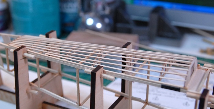
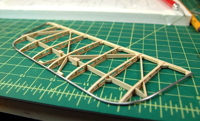
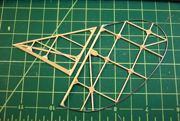
With the vertical stabilizer and rudder complete, I moved on to the horizontal stabilizer and elevator. The construction on this was very similar to that of the wings in that it is mostly laser-cut ribs and strip wood for strengthening and connecting. Here you can see the ribs with the lower cap strip and strengthening strips:
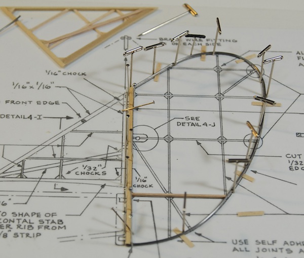
Here you can see the horizontal stabilizer going together on the plans sheet.
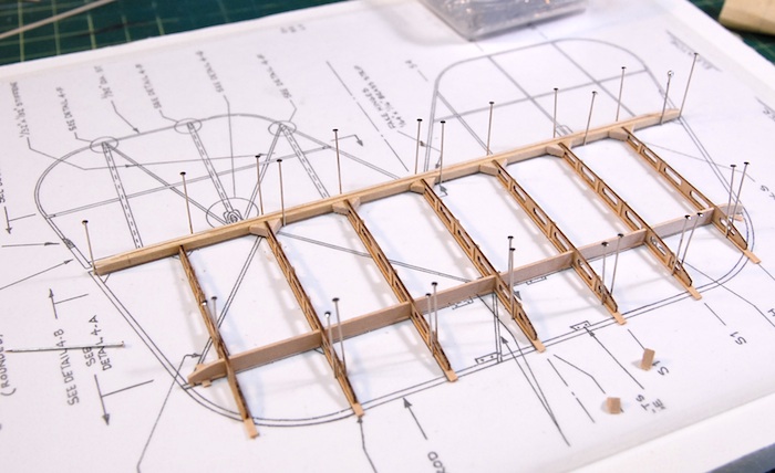
The leading edge on this piece is a steel rod, bent into shape after being heated up. The diagonal ribs are just strip wood cut and sanded into shape.
Once completed, this part can then be attached to the vertical stabilizer. Here you can see the connected pair drying after being stained.
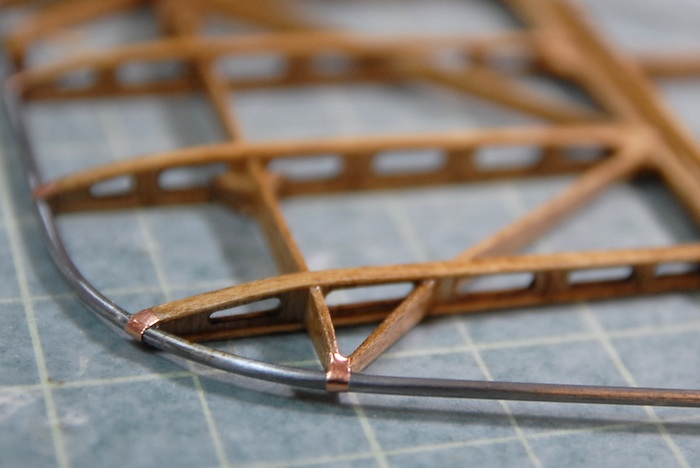
Once the stain and polyurethane was on the parts, I added the little bits of copper tape, which are meant to simulate the metal bands that hold the leading edge to the ribs.
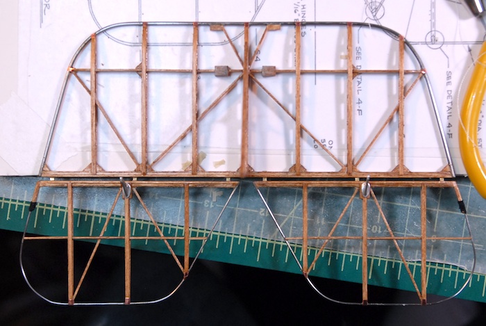
With that completed, the hinge slots were cut and the brass strips were cut for the fake hinges. Below you can see the elevators attached and the tiny fake hinges in place.
Before setting these parts aside, I did a little bit of rigging on the elevators and rudder, so that they are all ready to attach to the fuselage later on in the build.
With these parts done (for now), I was ready to move on to the next major step in the build...
The Fuselage!!
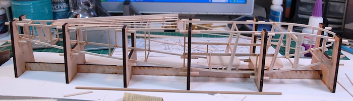
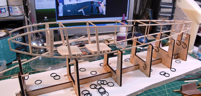
First and foremost, I had to put together a jig that will allow me to construct the fuselage in a square and true manner. The fit comes with a bunch of laser-cut parts that go together to form this jig, and below you can see it coming together.
The little dowels are so that the fuselage pieces can be attached with rubber bands later on. Also, the jig is glued down to that piece of foam board, so that it stays nice and straight through the process.
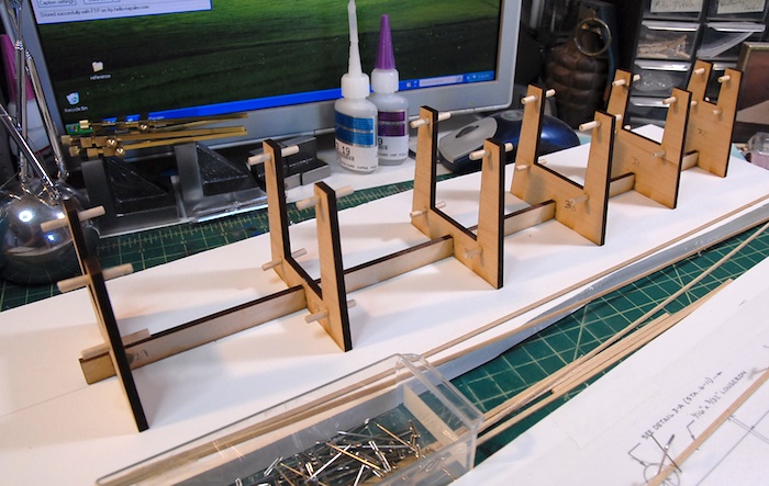
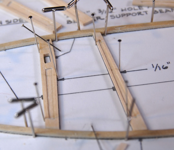
And finally, I've just soaked and bent the long pieces for one side of the fuselage frame. Here you can see it pinned down to the plans, with a few of the frame bits glued in (on the left side).
I've found that I'm not happy with the construction method for the three middle ribs. The pieces are supposed to have a mortise cut into each side of the rib, which is itself 1/16" thick. I've found that it is quite difficult to do this in a manner that doesn't look terrible. The wood tends to flake apart, or just look sloppy when I try to cut such a small amount out of it. Rather than keep trying or just settling for either non-mortised parts or sloppy-looking parts, I've decided to get some strips of very thin wood and attempt to build a sandwich-style rib, since I think cutting holes in thin wood will end up looking better than the carved-mortise version. I should end up with a part that looks just like it was carved out, except much cleaner and with much less hassle.
Tune in next time to see if my plan works ;)
With the vertical stabilizer and rudder complete, I moved on to the horizontal stabilizer and elevator. The construction on this was very similar to that of the wings in that it is mostly laser-cut ribs and strip wood for strengthening and connecting. Here you can see the ribs with the lower cap strip and strengthening strips:
Here you can see the horizontal stabilizer going together on the plans sheet.
The leading edge on this piece is a steel rod, bent into shape after being heated up. The diagonal ribs are just strip wood cut and sanded into shape.
Once completed, this part can then be attached to the vertical stabilizer. Here you can see the connected pair drying after being stained.
Once the stain and polyurethane was on the parts, I added the little bits of copper tape, which are meant to simulate the metal bands that hold the leading edge to the ribs.
With that completed, the hinge slots were cut and the brass strips were cut for the fake hinges. Below you can see the elevators attached and the tiny fake hinges in place.
Before setting these parts aside, I did a little bit of rigging on the elevators and rudder, so that they are all ready to attach to the fuselage later on in the build.
With these parts done (for now), I was ready to move on to the next major step in the build...
The Fuselage!!
First and foremost, I had to put together a jig that will allow me to construct the fuselage in a square and true manner. The fit comes with a bunch of laser-cut parts that go together to form this jig, and below you can see it coming together.
The little dowels are so that the fuselage pieces can be attached with rubber bands later on. Also, the jig is glued down to that piece of foam board, so that it stays nice and straight through the process.
And finally, I've just soaked and bent the long pieces for one side of the fuselage frame. Here you can see it pinned down to the plans, with a few of the frame bits glued in (on the left side).
I've found that I'm not happy with the construction method for the three middle ribs. The pieces are supposed to have a mortise cut into each side of the rib, which is itself 1/16" thick. I've found that it is quite difficult to do this in a manner that doesn't look terrible. The wood tends to flake apart, or just look sloppy when I try to cut such a small amount out of it. Rather than keep trying or just settling for either non-mortised parts or sloppy-looking parts, I've decided to get some strips of very thin wood and attempt to build a sandwich-style rib, since I think cutting holes in thin wood will end up looking better than the carved-mortise version. I should end up with a part that looks just like it was carved out, except much cleaner and with much less hassle.
Tune in next time to see if my plan works ;)
Wing Skids and Tail Parts
27 - March - 2011 - 20:07
As the building continues, I've finally completed all the little details on the wings. There were lots of little metal fittings, bits of rigging, and wooden supports that go along with the wings that all needed to be built before I moved on. For example, you can see below, the supports that go between the upper and lower wings. These were made from laser cut basswood with cast metal fittings on each end. Unfortunately, the notches that the cast metal fit into were not laser cut into the parts, so these took quite a bit of carving, sanding and filing in order to shape the wooden parts correctly. Once the metal parts were fitted, then the wooden middle needed to be sanded round and the metal ends polished to a shine.
In this image, the parts are drying after having been stained to match the rest of the model.
Similarly, the below part is the support that goes between the upper center wing section and the top of the fuselage. A similar carving/sanding/filing technique was required on these in order to get the metal end fittings integrated.
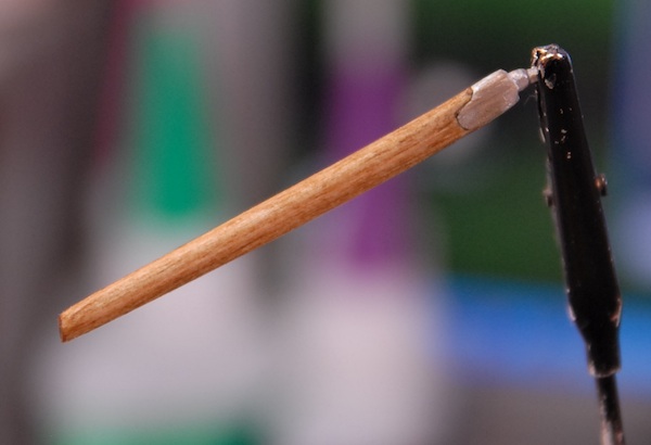
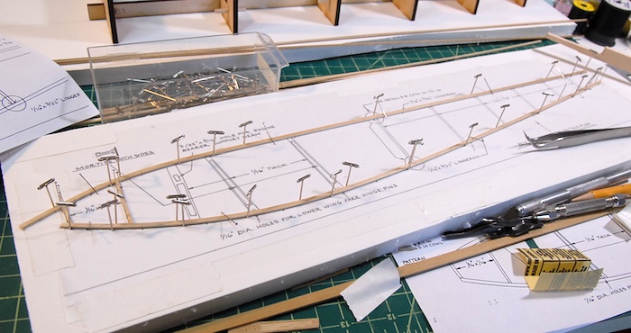
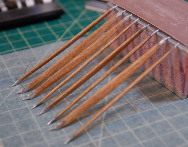
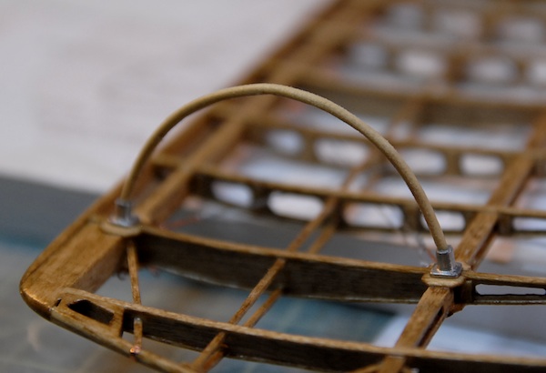
Also on the list of odds and ends were the skids that go on the bottom of the lower wings. On the real plane these were installed to help prevent catching a wing tip on a messy landing. On the model, they are made from a bent piece of wood. Since this bend was somewhat extreme, given that it was a 1/16" x 1/16" piece of wood, I decided to try a few new techniques for prepping the wood for bending. I tried wrapping it in a wet paper towel and then microwaving that, but didn't really have any luck there. Finally I just settled on good old fashioned soaking of the wood for an hour or so each. Below you can see the wood parts pinned down to the plans as they dry.
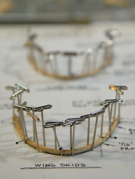
And here are the skids installed on the bottom of the wing, prior to stain and polyurethane.
That pretty much wrapped up the miscellaneous wing parts (there were a few others, like the king posts on the upper wings, but I don't have photos of those), so I finally got to move along to some non-wing parts.
First on the list are the tail surfaces. I started with the vertical stabilizer and rudder. The vertical stabilizer was a quick build, since it was just strip wood, pinned over the plan and glued in place. The rudder was a little more complicated, but still fairly simple. Like the wings, the rudder has a trailing edge made of bent wire. I used the same technique as I had previously to make the wire easier to work with. This involved annealing the wire, using a cooking torch (like for making creme brulee) to get the wire red hot and then let it cool back down again. This makes it a bit softer after it cools and easier to work with.
Below you can see the bent wire pinned in place and shimmed off the plans just a bit (so that it is centered to the leading edge) with the first of the ribs glued in place.
I've just finished the rudder, which was also pretty much just simple strip wood, cut, sanded and glued in place. Below you can see the completed parts. They still need to be stained, polyurethaned and then fitted with a few metal parts, but that'll come later, once the elevator is done. I've got to wait until the elevator is done because the bottom of the vertical stabilizer needs to be sanded to fit the top of the elevator so they both need to be complete before I can do the final fitting and then stain, etc.
The finished parts:
In this image, the parts are drying after having been stained to match the rest of the model.
Similarly, the below part is the support that goes between the upper center wing section and the top of the fuselage. A similar carving/sanding/filing technique was required on these in order to get the metal end fittings integrated.
Also on the list of odds and ends were the skids that go on the bottom of the lower wings. On the real plane these were installed to help prevent catching a wing tip on a messy landing. On the model, they are made from a bent piece of wood. Since this bend was somewhat extreme, given that it was a 1/16" x 1/16" piece of wood, I decided to try a few new techniques for prepping the wood for bending. I tried wrapping it in a wet paper towel and then microwaving that, but didn't really have any luck there. Finally I just settled on good old fashioned soaking of the wood for an hour or so each. Below you can see the wood parts pinned down to the plans as they dry.
And here are the skids installed on the bottom of the wing, prior to stain and polyurethane.
That pretty much wrapped up the miscellaneous wing parts (there were a few others, like the king posts on the upper wings, but I don't have photos of those), so I finally got to move along to some non-wing parts.
First on the list are the tail surfaces. I started with the vertical stabilizer and rudder. The vertical stabilizer was a quick build, since it was just strip wood, pinned over the plan and glued in place. The rudder was a little more complicated, but still fairly simple. Like the wings, the rudder has a trailing edge made of bent wire. I used the same technique as I had previously to make the wire easier to work with. This involved annealing the wire, using a cooking torch (like for making creme brulee) to get the wire red hot and then let it cool back down again. This makes it a bit softer after it cools and easier to work with.
Below you can see the bent wire pinned in place and shimmed off the plans just a bit (so that it is centered to the leading edge) with the first of the ribs glued in place.
I've just finished the rudder, which was also pretty much just simple strip wood, cut, sanded and glued in place. Below you can see the completed parts. They still need to be stained, polyurethaned and then fitted with a few metal parts, but that'll come later, once the elevator is done. I've got to wait until the elevator is done because the bottom of the vertical stabilizer needs to be sanded to fit the top of the elevator so they both need to be complete before I can do the final fitting and then stain, etc.
The finished parts:
And One Month Later....
13 - March - 2011 - 19:52
The wings are all rigged and nearly complete!
After a few weeks of tying tiny little copper fitting to short lengths of string, I managed to tie at least a few on to the model itself. I managed to come up with a fairly successful system where I tied all of the string to the little copper turnbuckles first and then tied them to the wing itself. I originally was doing one string at a time, tying the turnbuckle to the string and then the string to the model, but found this to be pretty slow going.
Here you can see a bunch of the pre-tied turnbuckles ready to go onto the lower wing panels. I have found that some of my ship-modeling skills have been helpful when it comes to knots and such.
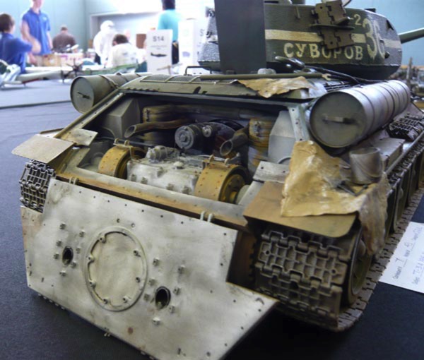
Once I had all of the rigging in the wings complete, then it was time to add various other copper and white metal fittings. This gave me the opportunity to use a new toy I purchased at the beginning of this project. It is a 'Hold and Fold' photo-etch workstation from the nice folks at The Small Shop. As you can see in the photo, it is a billet aluminum clamp-like device that let's me clamp a bit of photo-etched metal down (very precisely) and then fold it using that great big razor blade. I got to use it a bit today to crease some of the rigging plate things that go on to the wings and will eventually be clamped between the wing and the posts that connect the two wings.
Once I had all of the rigging in the wings complete, then it was time to add various other copper and white metal fittings. This gave me the opportunity to use a new toy I purchased at the beginning of this project. It is a 'Hold and Fold' photo-etch workstation from the nice folks at The Small Shop. As you can see in the photo, it is a billet aluminum clamp-like device that let's me clamp a bit of photo-etched metal down (very precisely) and then fold it using that great big razor blade. I got to use it a bit today to crease some of the rigging plate things that go on to the wings and will eventually be clamped between the wing and the posts that connect the two wings.
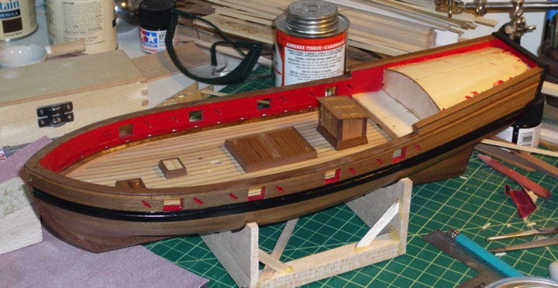
I also spent a bit of time filing, sanding and polishing a few cast white metal parts which were put together to become the little pulleys that control the ailerons. I've still got two more to add, but here are the tops ones in place:
That's all for now! With the wings nearly complete, I'll soon be moving on to the tail parts. Until next time.
After a few weeks of tying tiny little copper fitting to short lengths of string, I managed to tie at least a few on to the model itself. I managed to come up with a fairly successful system where I tied all of the string to the little copper turnbuckles first and then tied them to the wing itself. I originally was doing one string at a time, tying the turnbuckle to the string and then the string to the model, but found this to be pretty slow going.
Here you can see a bunch of the pre-tied turnbuckles ready to go onto the lower wing panels. I have found that some of my ship-modeling skills have been helpful when it comes to knots and such.
Once I had all of the rigging in the wings complete, then it was time to add various other copper and white metal fittings. This gave me the opportunity to use a new toy I purchased at the beginning of this project. It is a 'Hold and Fold' photo-etch workstation from the nice folks at The Small Shop. As you can see in the photo, it is a billet aluminum clamp-like device that let's me clamp a bit of photo-etched metal down (very precisely) and then fold it using that great big razor blade. I got to use it a bit today to crease some of the rigging plate things that go on to the wings and will eventually be clamped between the wing and the posts that connect the two wings.
Once I had all of the rigging in the wings complete, then it was time to add various other copper and white metal fittings. This gave me the opportunity to use a new toy I purchased at the beginning of this project. It is a 'Hold and Fold' photo-etch workstation from the nice folks at The Small Shop. As you can see in the photo, it is a billet aluminum clamp-like device that let's me clamp a bit of photo-etched metal down (very precisely) and then fold it using that great big razor blade. I got to use it a bit today to crease some of the rigging plate things that go on to the wings and will eventually be clamped between the wing and the posts that connect the two wings.
I also spent a bit of time filing, sanding and polishing a few cast white metal parts which were put together to become the little pulleys that control the ailerons. I've still got two more to add, but here are the tops ones in place:
That's all for now! With the wings nearly complete, I'll soon be moving on to the tail parts. Until next time.
Wing Staining & Rigging
12 - February - 2011 - 17:12
Work on the wings continues...
Since the last post, I've finished the staining of the wing panels and then put a few coats of a semi-gloss water-based polyurethane. This is to seal up the wood as well as to add some depth to the finish. Overall, I am pretty happy with the way the finish turned out and it makes a fantastic contract to the white metal and copper parts. Here is an image of one of the stained and finished lower wing panels:
It did take quite a while to get the stain and poly on there, since it all had to be brushed on by hand. I feel that the results were worth it, though.
The next step in the process was to add the adhesive copper tape strips to the ends of the ribs at the trailing edge. These are to simulate the bands of metal that clamped on the trailing edge on the real plane. This was pretty easy, since the copper tape is very malleable, and can be smoothed down with a fingernail and the edges burnished smooth with some tweezers.
Here is a photo of the aileron edge with tape applied. I really like the way the copper looks against the stained wood.
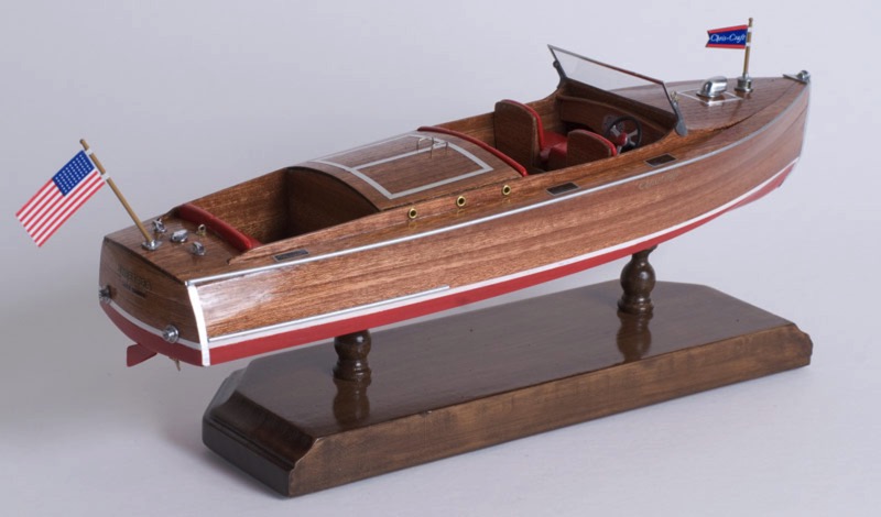
Next, I pulled out a few of the white metal parts and had a go at polishing them up a bit. They come with a fairly matte finish and with some imperfections in the casting. I bit of work with various sanding sticks and they shine up nicely. Here you can see the aileron control horns attached to the ailerons, and also the fake hinges (made of strip brass) sticking off of the back of the parts.
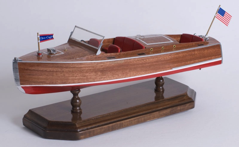
Now, I am on to the rigging step, where all the turnbuckles and wires that maintain the internal wing structure are put into place. I'm finding that some of my experience on the Armed Virginia Sloop model is coming in handy, in that I can reuse some of the rigging techniques that I learned on that project. Here is a pic of the first part that has been completed:
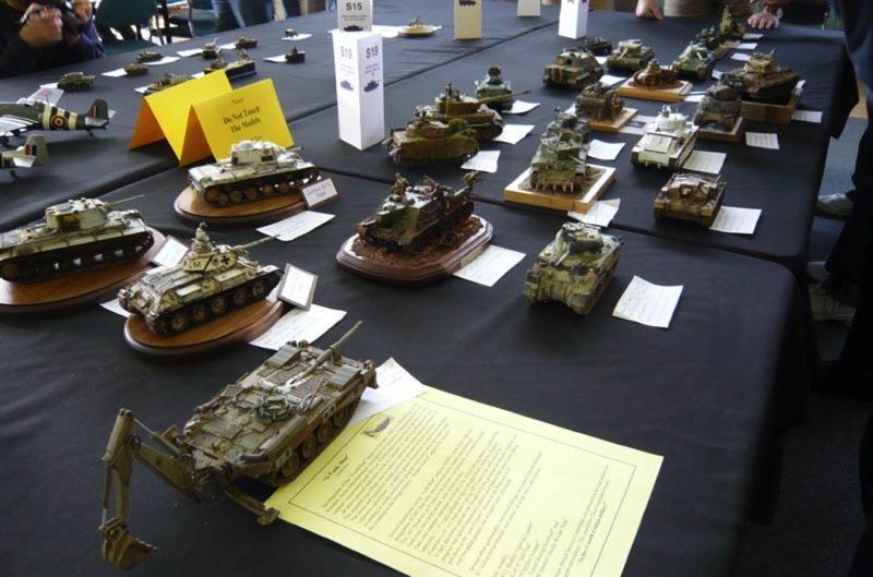
This rigging stuff, while not too complicated, is a bit fiddly and generally slow-going. I'm expecting that I'll probably spend the next couple of weeks on this, and will have another update once that is complete. Stay tuned until then!
Since the last post, I've finished the staining of the wing panels and then put a few coats of a semi-gloss water-based polyurethane. This is to seal up the wood as well as to add some depth to the finish. Overall, I am pretty happy with the way the finish turned out and it makes a fantastic contract to the white metal and copper parts. Here is an image of one of the stained and finished lower wing panels:
It did take quite a while to get the stain and poly on there, since it all had to be brushed on by hand. I feel that the results were worth it, though.
The next step in the process was to add the adhesive copper tape strips to the ends of the ribs at the trailing edge. These are to simulate the bands of metal that clamped on the trailing edge on the real plane. This was pretty easy, since the copper tape is very malleable, and can be smoothed down with a fingernail and the edges burnished smooth with some tweezers.
Here is a photo of the aileron edge with tape applied. I really like the way the copper looks against the stained wood.
Next, I pulled out a few of the white metal parts and had a go at polishing them up a bit. They come with a fairly matte finish and with some imperfections in the casting. I bit of work with various sanding sticks and they shine up nicely. Here you can see the aileron control horns attached to the ailerons, and also the fake hinges (made of strip brass) sticking off of the back of the parts.
Now, I am on to the rigging step, where all the turnbuckles and wires that maintain the internal wing structure are put into place. I'm finding that some of my experience on the Armed Virginia Sloop model is coming in handy, in that I can reuse some of the rigging techniques that I learned on that project. Here is a pic of the first part that has been completed:
This rigging stuff, while not too complicated, is a bit fiddly and generally slow-going. I'm expecting that I'll probably spend the next couple of weeks on this, and will have another update once that is complete. Stay tuned until then!
Wings Done!
30 - January - 2011 - 20:06
Another long lost update to the blog! Although this time I have a better excuse. I haven't updated before now because everything that I have been doing in between this and the last post has been pretty boring. Not that it's been boring to work on, per se, but rather it's almost the exact same tasks I've already blogged about, just more so. So rather than post about how I've sanded ANOTHER 40 ribs, I figured I'd just wait until there was something more interesting to see.
I've finally finished the main construction on the four wing panels. This includes most all of the wooden parts, and just a few metal bits. The only metal parts that are on there at the moment are either structural (like the trailing edge wire) or would be too tricky to install later in the construction process (like the little eyelets in the middle areas). So with that taken care of, I can finally apply the stain and polyurethane to the wings in preparation for further construction. Below you can see the completed wing panels.
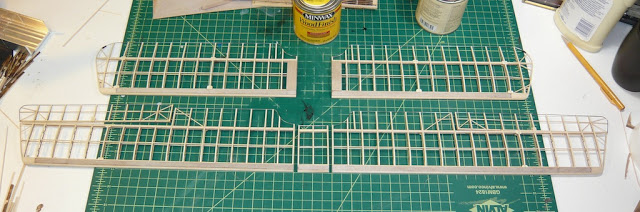
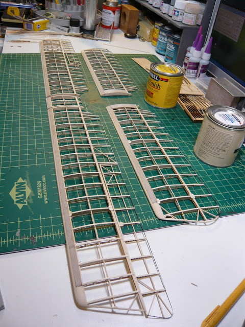
Once the stain and poly are applied, I'll be able to rig the internal wires on the wings and apply various other braces and supports. Here is a snapshot of the wing panels hung up to dry after being stained.
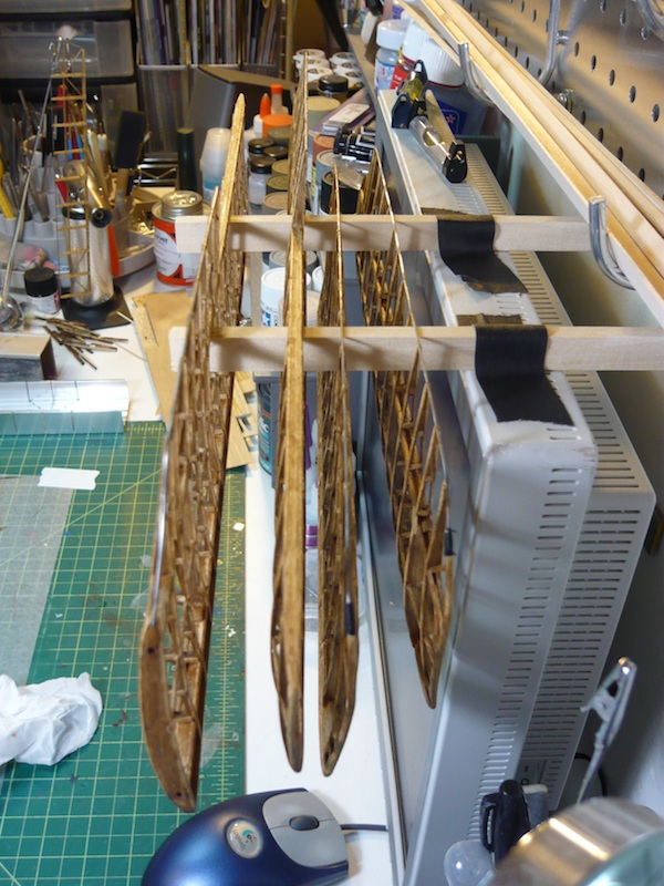
Stay tuned for more action-packed adventure!
I've finally finished the main construction on the four wing panels. This includes most all of the wooden parts, and just a few metal bits. The only metal parts that are on there at the moment are either structural (like the trailing edge wire) or would be too tricky to install later in the construction process (like the little eyelets in the middle areas). So with that taken care of, I can finally apply the stain and polyurethane to the wings in preparation for further construction. Below you can see the completed wing panels.
Once the stain and poly are applied, I'll be able to rig the internal wires on the wings and apply various other braces and supports. Here is a snapshot of the wing panels hung up to dry after being stained.
Stay tuned for more action-packed adventure!
Long Lost Update...
09 - November - 2010 - 21:15
At long last, I'm updating the blog again. In the interim, I spent a week in Hawaii, played through Fallout: New Vegas, and have just been busy with life in general. But last weekend, I finally got back to working on the model again. Here is where things stand thus far...
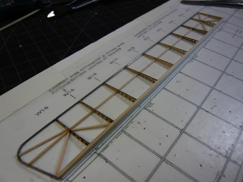
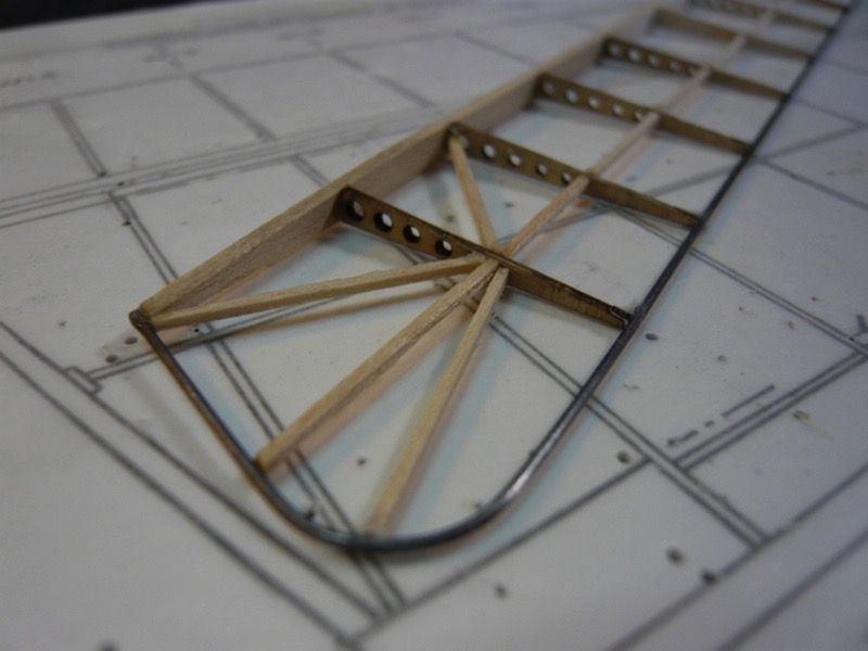
I've finished the wood work on one of the upper wing panels. This includes both the wing panel and the aileron. While the panal isn't DONE yet, it's reached the point that I'll need to stain and seal it, so I decided it would probably be best if I built all the wing panels and THEN did the staining and sealing. Once that is done, there are a variety of metal and string parts that go on the wings as well.
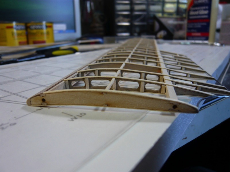
As you can see in the various photos here, I'm making slow but steady progress.
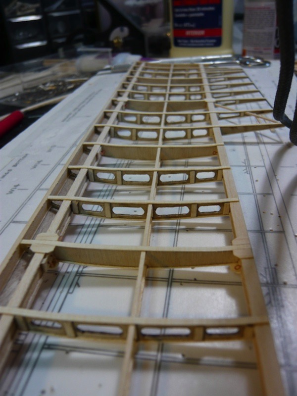
Starting on the next wing panel, I'm taking a bit from what I learned from the first and making sure I have much of the sanding and fitting done beforehand. This means that I've got to do all the monotonous filing first, but it should make assembly go much faster overall.
Here is a photo of a before and after wing rib. You can see how I'm also sanding off the blackening on the edges of the cutouts. This blackening is from the laser cutting of the parts, and I feel that removing it will add a bit to the scale fidelity of the model. The drawback is that it's a royal pain in the butt, and some of these wing ribs are pretty fragile and are easily broken while sanding. Hooray for super glue!
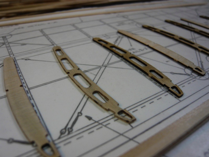
Stay tuned for further adventures in modeling!
I've finished the wood work on one of the upper wing panels. This includes both the wing panel and the aileron. While the panal isn't DONE yet, it's reached the point that I'll need to stain and seal it, so I decided it would probably be best if I built all the wing panels and THEN did the staining and sealing. Once that is done, there are a variety of metal and string parts that go on the wings as well.
As you can see in the various photos here, I'm making slow but steady progress.
Starting on the next wing panel, I'm taking a bit from what I learned from the first and making sure I have much of the sanding and fitting done beforehand. This means that I've got to do all the monotonous filing first, but it should make assembly go much faster overall.
Here is a photo of a before and after wing rib. You can see how I'm also sanding off the blackening on the edges of the cutouts. This blackening is from the laser cutting of the parts, and I feel that removing it will add a bit to the scale fidelity of the model. The drawback is that it's a royal pain in the butt, and some of these wing ribs are pretty fragile and are easily broken while sanding. Hooray for super glue!
Stay tuned for further adventures in modeling!
Curtis Jenny Progress
11 - September - 2010 - 08:05
Here is a little update on what I've been up to. I've started a new project. This time it is a wooden/metal kit instead of plastic. It is a World War I era biplane, and will end up as a static display (non flying) model with all the internal details visible.
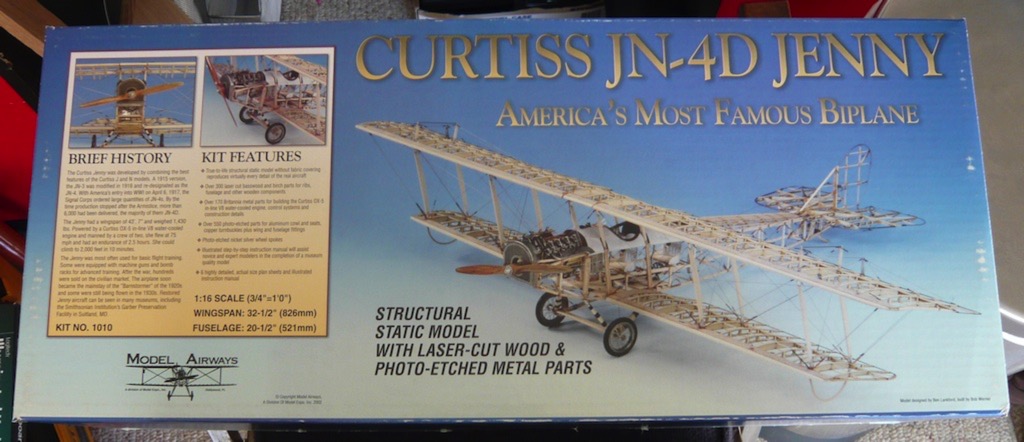

This one is both similar and quite different from the wooden ship that I previously built. This project has generally the same raw materials: laser-cut wood, stock strip wood, cast white metal, etc. The big difference this time around is that I'm not following a course on the projects construction. This just means that I have to follow the somewhat rough instructions that come with the model itself and do much more deciphering of the sheet plans. This isn't a bad thing, just a different challenge.
So, I've decided to start with one of the top wing panels, in order to go through most of it's construction, and learn what I can in the process. In theory, this should confine all my screw-ups to just one wing panel, making for less fixing later and smoother/faster construction of the other three panels. With that said, here are some photos of my progress thus far:
Initial wing ribs layout.
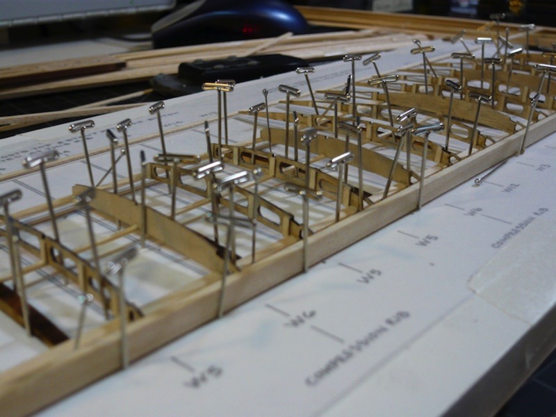
Photo-etched fittings for later wire rigging.
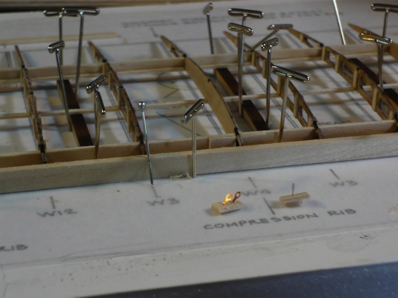
Bending the wing tip rib.
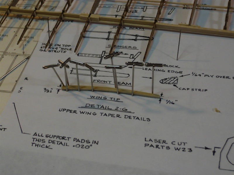
More wing tip construction.
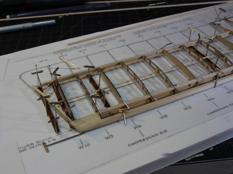
With the thin plywood leading edge cap strip.
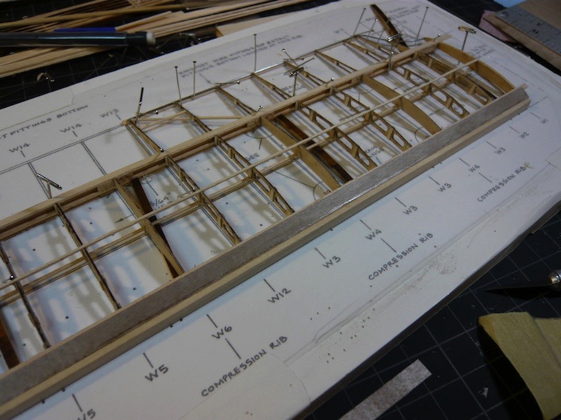
Progress has been a bit slow so far, as I've not had as much free time as I would like. But, stay tuned for more progress, some wood stain color tests and further adventures in modeling!
This one is both similar and quite different from the wooden ship that I previously built. This project has generally the same raw materials: laser-cut wood, stock strip wood, cast white metal, etc. The big difference this time around is that I'm not following a course on the projects construction. This just means that I have to follow the somewhat rough instructions that come with the model itself and do much more deciphering of the sheet plans. This isn't a bad thing, just a different challenge.
So, I've decided to start with one of the top wing panels, in order to go through most of it's construction, and learn what I can in the process. In theory, this should confine all my screw-ups to just one wing panel, making for less fixing later and smoother/faster construction of the other three panels. With that said, here are some photos of my progress thus far:
Initial wing ribs layout.
Photo-etched fittings for later wire rigging.
Bending the wing tip rib.
More wing tip construction.
With the thin plywood leading edge cap strip.
Progress has been a bit slow so far, as I've not had as much free time as I would like. But, stay tuned for more progress, some wood stain color tests and further adventures in modeling!
A Sneak Preview
19 - June - 2010 - 08:22
Just a quick post to bring things up to date. Here's a quick look at upcoming projects.
This past week I received a kit for another wooden and metal model. This one is a WWI biplane, the Curtiss JN-4D 'Jenny'. I'm hoping that it'll be a challenging build, similar to the Sloop build, except with much more metal and photo-etch. I'm actually hoping to set up a time-lapse recording method for this build, using an old computer, and a webcam. But since I think this might take me a little bit to get set up and tested, I'm going to hold off on starting this build for a little while.

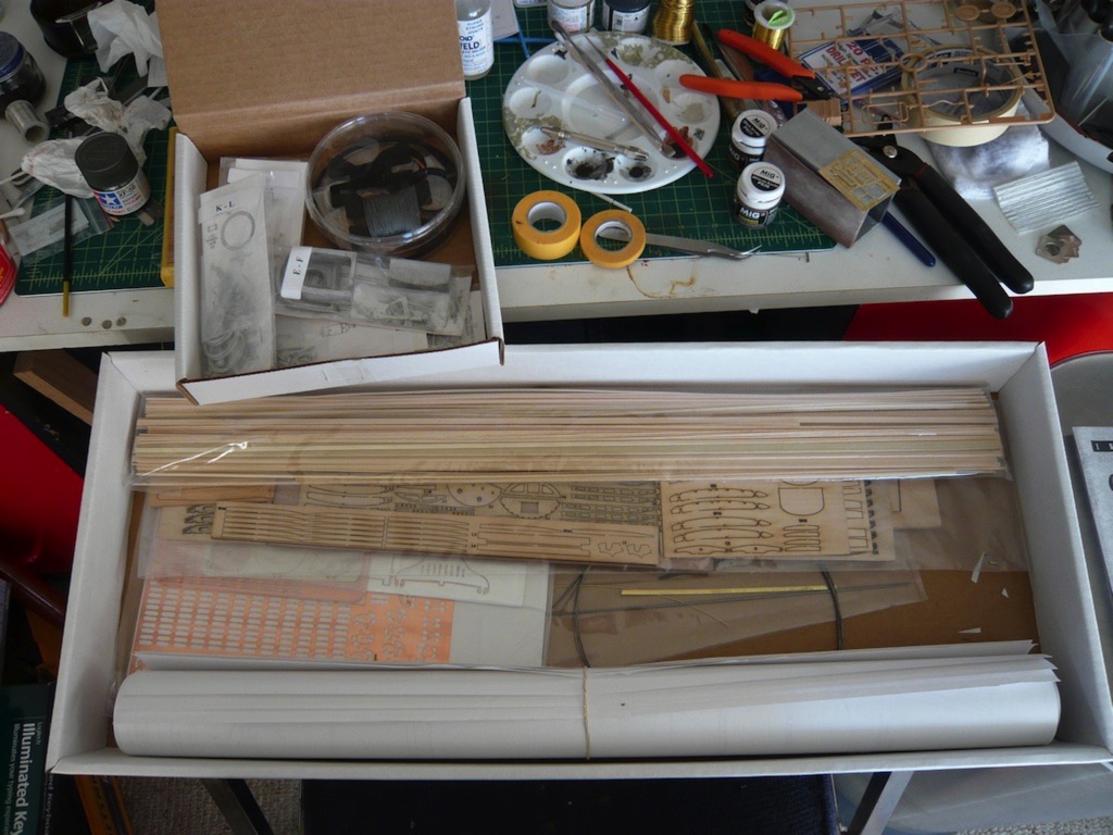
So, in the meantime, after wrapping up the motorcycle model (which I plan on doing today), I'll be putting this one together:
It should be a quick, fun build, since there isn't any engine. I was in the mood to make something shiny before I start on a longer build, so I figure I can crank through this one in a few weeks, and should be able to test out my time-lapse setup in the process :)
And there we have it. That's my modeling progress brought up to date. Party on.
This past week I received a kit for another wooden and metal model. This one is a WWI biplane, the Curtiss JN-4D 'Jenny'. I'm hoping that it'll be a challenging build, similar to the Sloop build, except with much more metal and photo-etch. I'm actually hoping to set up a time-lapse recording method for this build, using an old computer, and a webcam. But since I think this might take me a little bit to get set up and tested, I'm going to hold off on starting this build for a little while.
So, in the meantime, after wrapping up the motorcycle model (which I plan on doing today), I'll be putting this one together:
It should be a quick, fun build, since there isn't any engine. I was in the mood to make something shiny before I start on a longer build, so I figure I can crank through this one in a few weeks, and should be able to test out my time-lapse setup in the process :)
And there we have it. That's my modeling progress brought up to date. Party on.
Armed Virginia Sloop - And That's That
06 - December - 2009 - 20:21
After roughly ten months of work, cutting, sanding, gluing, painting, and tying, I think this one is finally done.
The past few weeks have mostly just been spent finishing the rigging. The final few steps were to add the anchors and clean up many of the tied-off strings. The swivel guns were finally glued in place and the thick anchor rope was formed into a coil on deck.
Overall this has been a very rewarding project, and I've learned an enormous amount about both working with wood on a small scale and about sailing ships themselves. But now I'm definitely ready for some non-wood projects! I've got a bit of a stockpile of plastic kits that I've built up over the past year, so keep an eye out for future updates on those.
Now, for some photos:
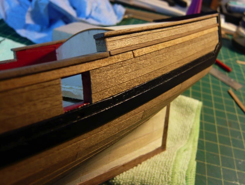
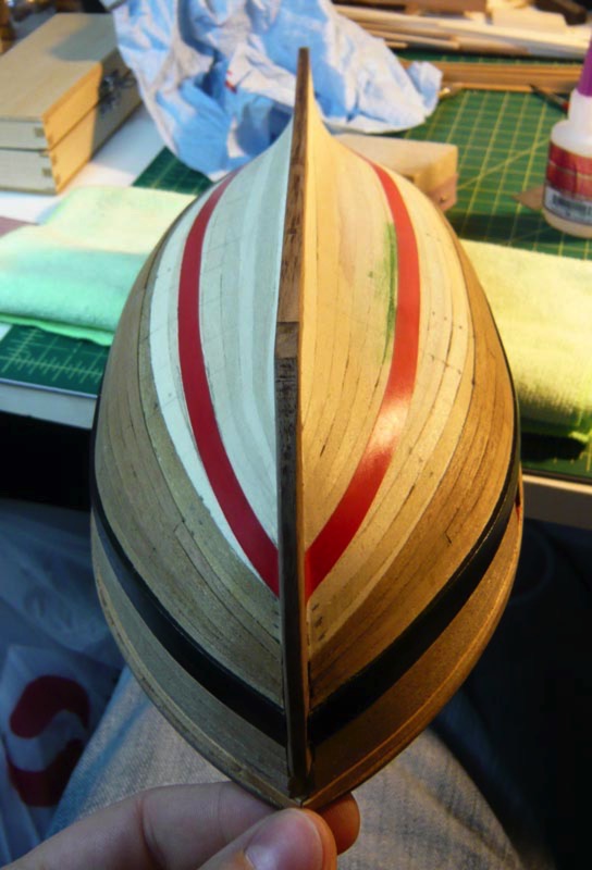
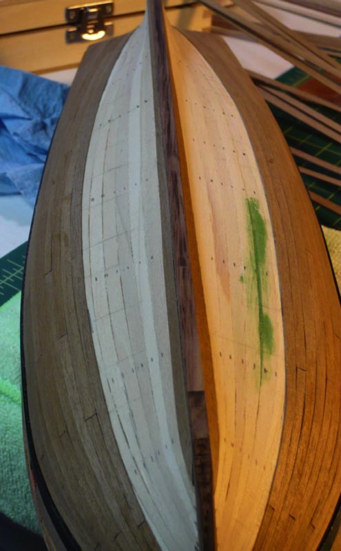
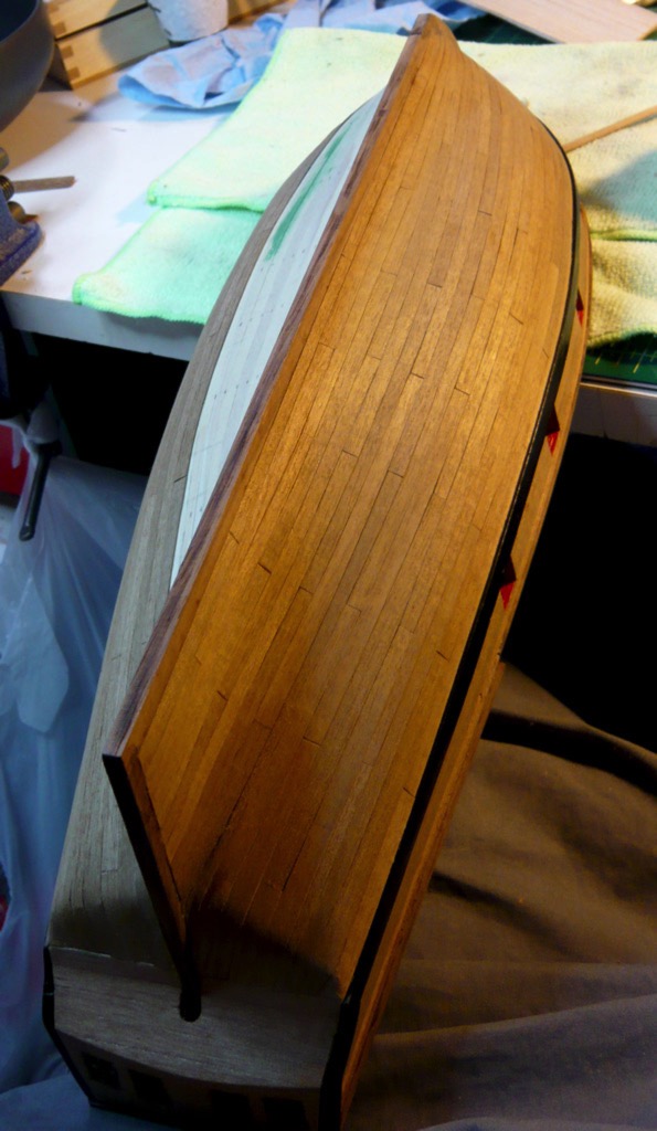
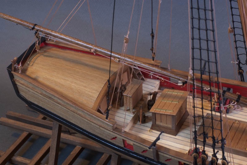
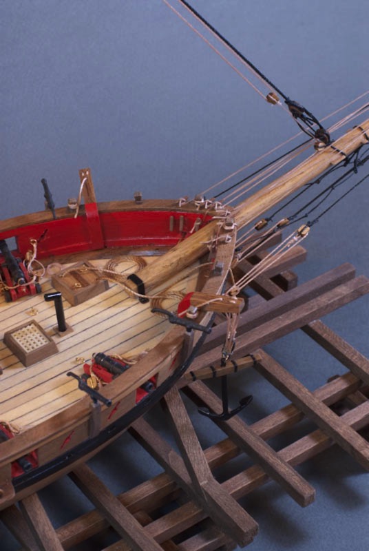
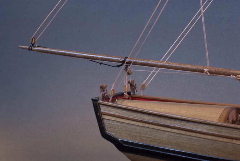
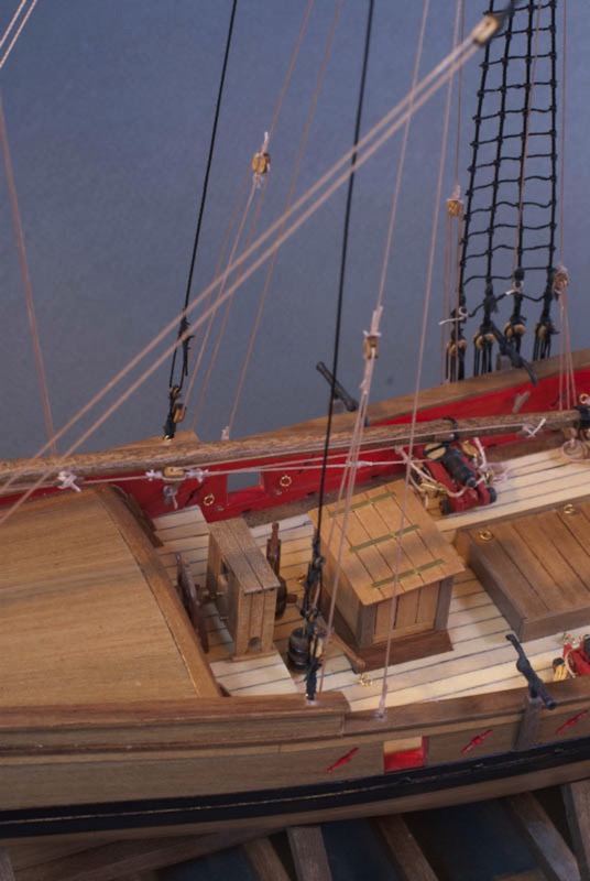
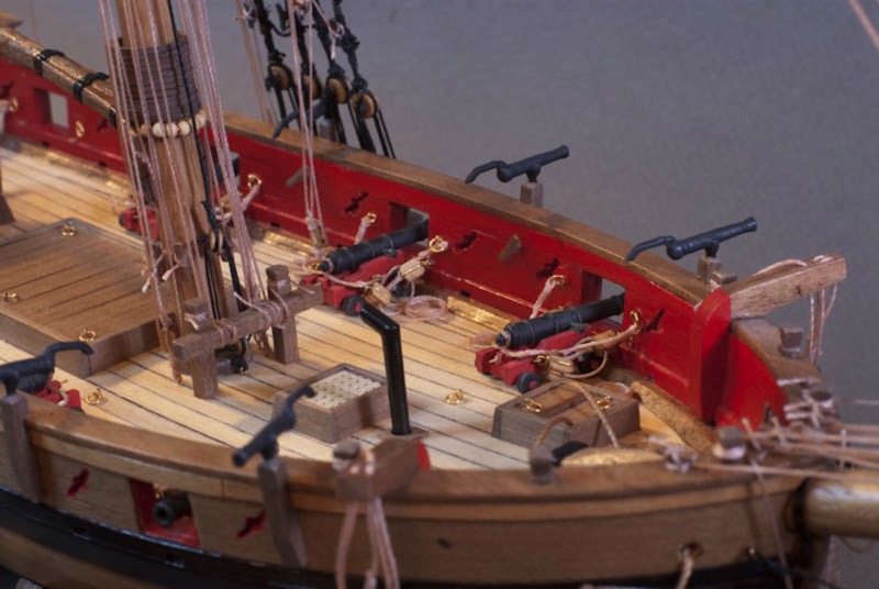
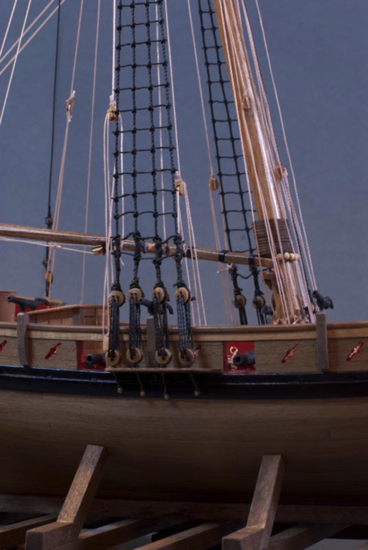
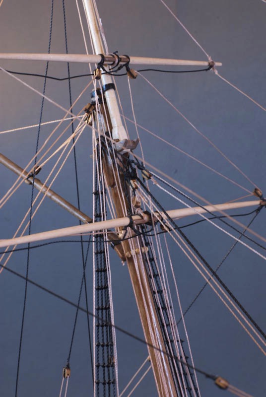
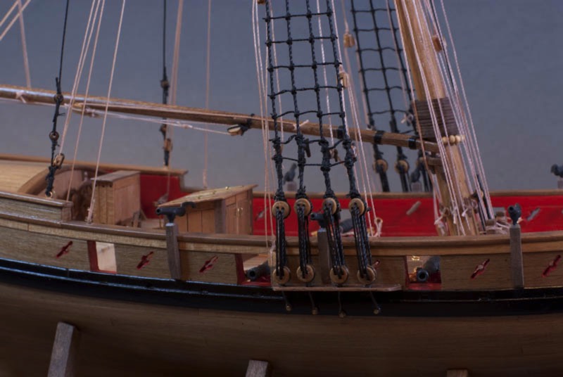
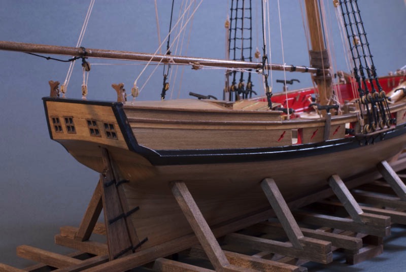
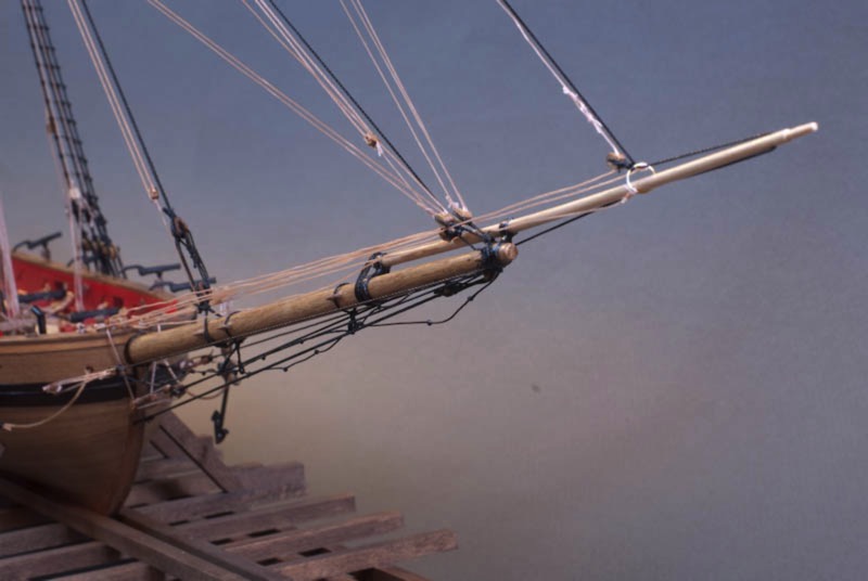
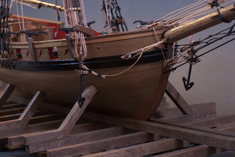
AVS - Rigging Update
01 - November - 2009 - 20:21
Just a quick update on my progress so far. Not a whole lot has changed since the last post. I've been fairly busy, but managed to get some more strings tied to the ship. Disclaimer: I left my camera at work on Friday, so these photos are just taken with my phone, and not touched by Photoshop, so they aren't quite as clean.
Anyway, I'm pretty much really all done with the standing rigging (with the exception of the ratlines on the shrouds, which I'll add later). Now, I'm mostly adding the lines that would run the sails up and down. I've also found that careful application of a lighter to the strings, since they are synthetic, tightens them up nicely once everything is all tied and glued.
With that, here are a few photos of the new bits:
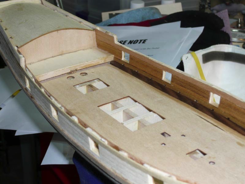
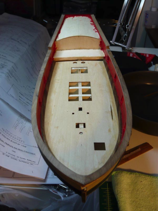
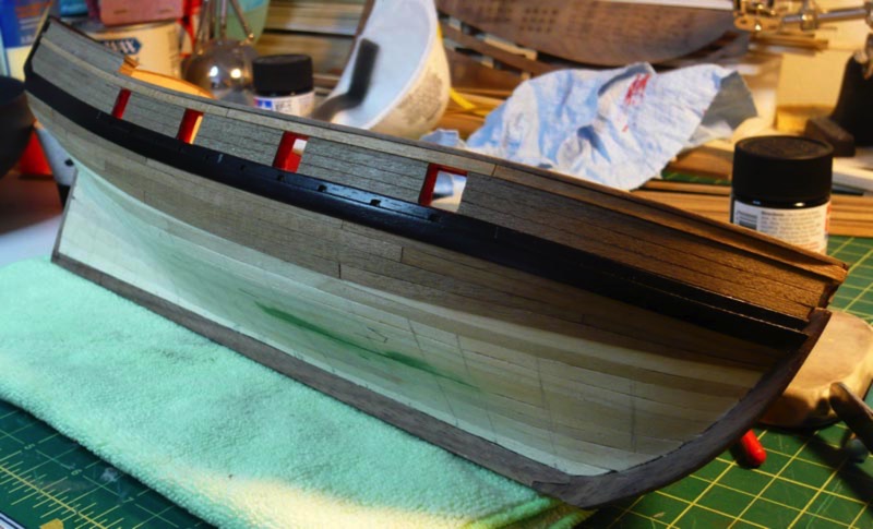
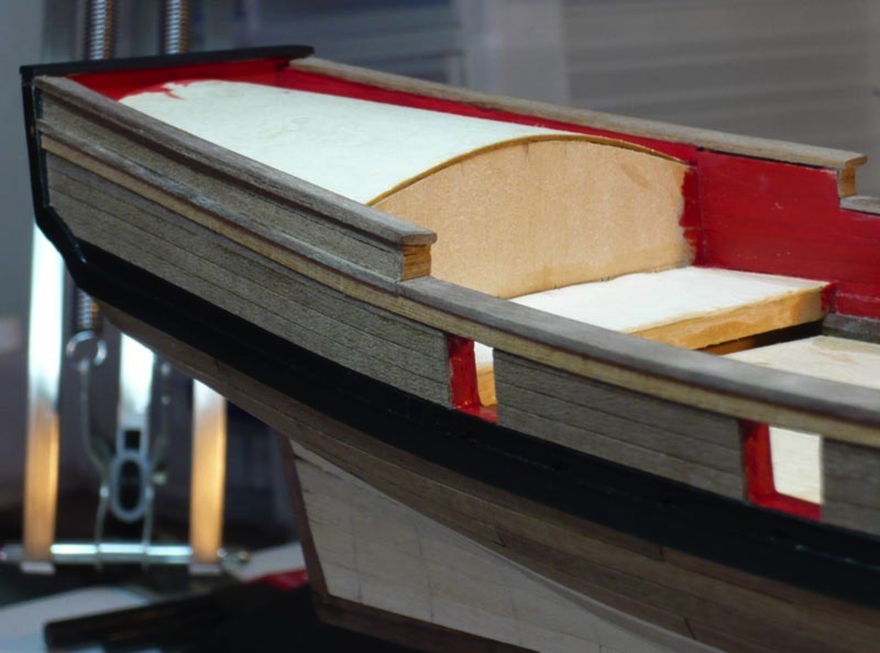
Armed Virginia Sloop - Masts and Rigging
25 - October - 2009 - 19:40
Finally, a long overdue update on the ship. I moved on from the bowsprit and formed the main mast, the topmast, the booms, and the yards. I settled on a technique for thinning the dowels that seemed to work pretty well: Since I didn't have a lathe, I put the dowels into my electric drill (being careful not to put them in TOO tight, since that leaves dents in the wood), and then set the drill up to the highest speed and just held sandpaper against it. This would be fairly painful using my bare hands, but I happened to have some of those silicon oven mitts, which let you hold very hot things (I had gotten them for smoking ribs). So, using the gloves, and holding 150 grit sandpaper against the spinning dowels, they were fairly quickly down to the proper diameter and taper.
After that, it was just a matter of building the trestle tree (where the main mast meets the top mast) and adding various extra bits and nubs to the yards and masts.

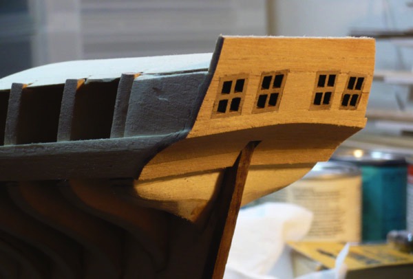
Below you can see the bases of the booms, with card stock wrapped around, painted and then with polyurethane on it, to simulate the iron bands that were on the real ships. You can also see the sail hoop things on the mast. Since my ship won't have sails on it, they just sit there on the mast. I took this opportunity to try out "Black It" metal blackening solution, which is supposed to chemically blacken various metals. In my case it really just turned them sort of rust colored. Although, since that looks fairly natural in the context, I decided to go with it.
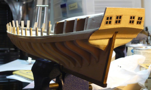
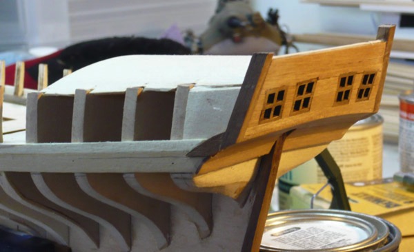
With all of the various wooden parts of the rigging complete, I moved on to the strings. The practicum that I am following had me start with the bowsprit rigging and then prep almost all of the rigging on the lower mast before actually gluing the mast in place. Below you can see the completed bowsprit rigging, as well as the partially-rigged lower mast and trestle tree. On the main mast, on a few of the strings have actually been connected to the ship itself, so many of them are hanging loose in a disorderly fashion, which explains their fairly messy appearance in the photos.
Ship trivia of the day: Currently I am mostly just dealing with what is called the 'standing rigging', which are the ropes that generally do not move when the sails go up and down, but instead serve to hold the various masts, etc in place. These ropes were usually coated with tar, to waterproof them, and so, on my model, are made from the black string.
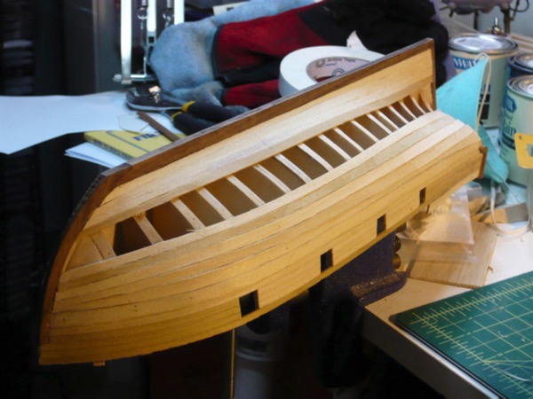
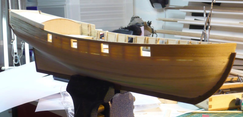
Here are a few photos of the upper rigging meeting the ship.
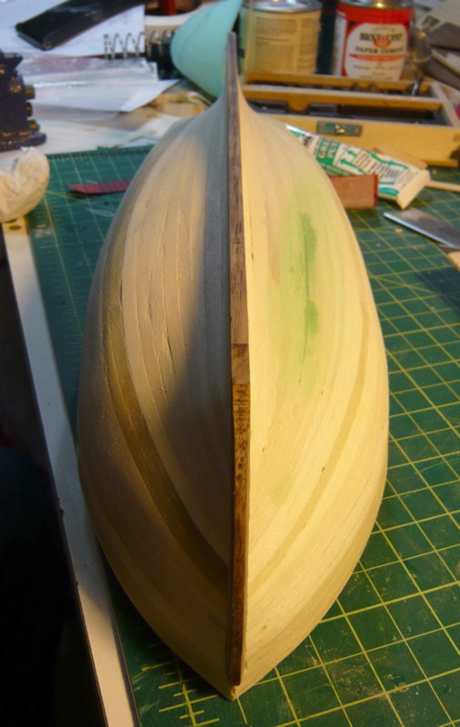
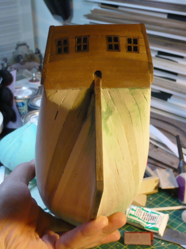
Finally, the ship in its current state. Standing rigging in progress, with mast and bowsprit attached. The rigging is moving along at a good pace so far, so I am hoping to increase the frequency of my updates on it :)
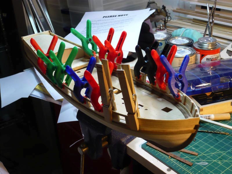
After that, it was just a matter of building the trestle tree (where the main mast meets the top mast) and adding various extra bits and nubs to the yards and masts.
Below you can see the bases of the booms, with card stock wrapped around, painted and then with polyurethane on it, to simulate the iron bands that were on the real ships. You can also see the sail hoop things on the mast. Since my ship won't have sails on it, they just sit there on the mast. I took this opportunity to try out "Black It" metal blackening solution, which is supposed to chemically blacken various metals. In my case it really just turned them sort of rust colored. Although, since that looks fairly natural in the context, I decided to go with it.
With all of the various wooden parts of the rigging complete, I moved on to the strings. The practicum that I am following had me start with the bowsprit rigging and then prep almost all of the rigging on the lower mast before actually gluing the mast in place. Below you can see the completed bowsprit rigging, as well as the partially-rigged lower mast and trestle tree. On the main mast, on a few of the strings have actually been connected to the ship itself, so many of them are hanging loose in a disorderly fashion, which explains their fairly messy appearance in the photos.
Ship trivia of the day: Currently I am mostly just dealing with what is called the 'standing rigging', which are the ropes that generally do not move when the sails go up and down, but instead serve to hold the various masts, etc in place. These ropes were usually coated with tar, to waterproof them, and so, on my model, are made from the black string.
Here are a few photos of the upper rigging meeting the ship.
Finally, the ship in its current state. Standing rigging in progress, with mast and bowsprit attached. The rigging is moving along at a good pace so far, so I am hoping to increase the frequency of my updates on it :)
Armed Virginia Sloop - Odds and Ends
27 - September - 2009 - 20:43
I was off on vacation for a week, so the updates lagged a bit behind. But, now I am back and have had a little time to work on the ship.
I don't really have any great insights to share this time around, so just a quick post to update my progress and show a few photos of where I am at the moment.
First off, I had to wrap up a few remaining deck fixtures. This included the little stairs to the top deck/roof, lots of little cleats, attaching all the bases for the swivel cannons, the swivel cannons themselves, various holes being drilled for future attachments, etc. Also, I added the channels, chainplates and deadeyes (those wings and round things sticking off the sides of the ship) in preparation for adding the masts and rigging.
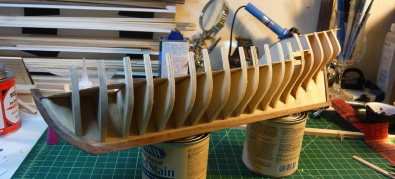
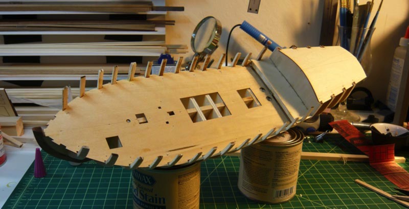
Next, since the ship is mostly just getting rigging stuff added from this point on, I built the real base, which is a model of the launching ways. This was built all from 1/4" basswood stock, cut to size, stained, and then glued into place. There was a little bit of fiddly work, getting all the proper angles cut into the upright support parts, but nothing too tough :)
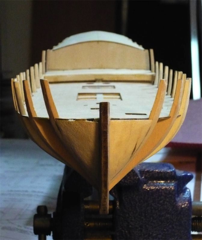
Finally, I've started work on the masts. First up was the bowsprit (big one) and the jibboom (little one). The bowsprit was fashioned from a 3/8" dowel which has to be slimmed down by using a combination of sanding drums in a dremel, and sanding the dowel while it is spinning in a drill. This was mostly quite a bit of experimentation, and I can't say that either method really worked all that well, but it got the job done. Anyhow, that's where I am now, with the bowsprit temporarily installed. Next up are various little fittings on the bowsprit, and then moving on to the main mast.
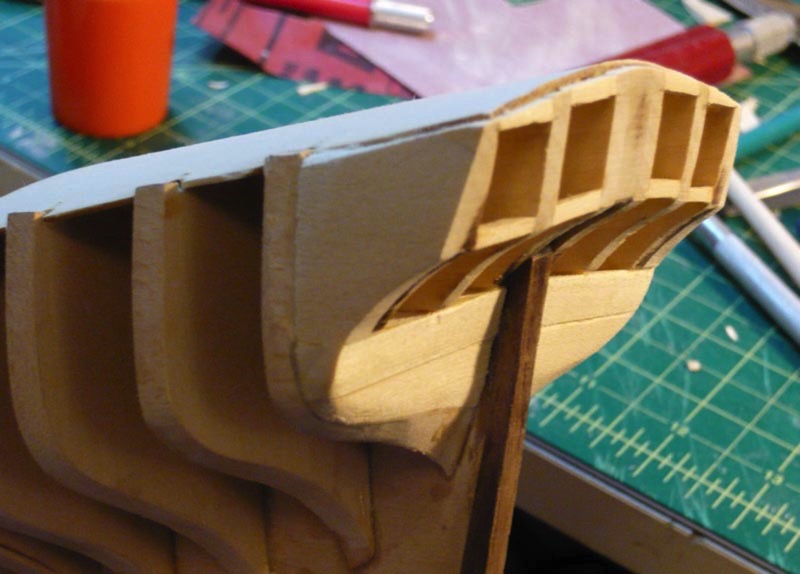
I don't really have any great insights to share this time around, so just a quick post to update my progress and show a few photos of where I am at the moment.
First off, I had to wrap up a few remaining deck fixtures. This included the little stairs to the top deck/roof, lots of little cleats, attaching all the bases for the swivel cannons, the swivel cannons themselves, various holes being drilled for future attachments, etc. Also, I added the channels, chainplates and deadeyes (those wings and round things sticking off the sides of the ship) in preparation for adding the masts and rigging.
Next, since the ship is mostly just getting rigging stuff added from this point on, I built the real base, which is a model of the launching ways. This was built all from 1/4" basswood stock, cut to size, stained, and then glued into place. There was a little bit of fiddly work, getting all the proper angles cut into the upright support parts, but nothing too tough :)
Finally, I've started work on the masts. First up was the bowsprit (big one) and the jibboom (little one). The bowsprit was fashioned from a 3/8" dowel which has to be slimmed down by using a combination of sanding drums in a dremel, and sanding the dowel while it is spinning in a drill. This was mostly quite a bit of experimentation, and I can't say that either method really worked all that well, but it got the job done. Anyhow, that's where I am now, with the bowsprit temporarily installed. Next up are various little fittings on the bowsprit, and then moving on to the main mast.
Armed Virginia Sloop - Getting Crowded On Deck
07 - September - 2009 - 22:00
Another small update today. This mostly consists of various deck furniture and fittings. First up are the boom crutches:
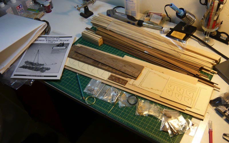
(very exciting, I know)
In the next photo, you can see the smokestack for the galley, the riding bitt (little rope rack thing in the left-middle, there) and the catheads (little arms that stick off the front. No cats harmed in the making of this model).
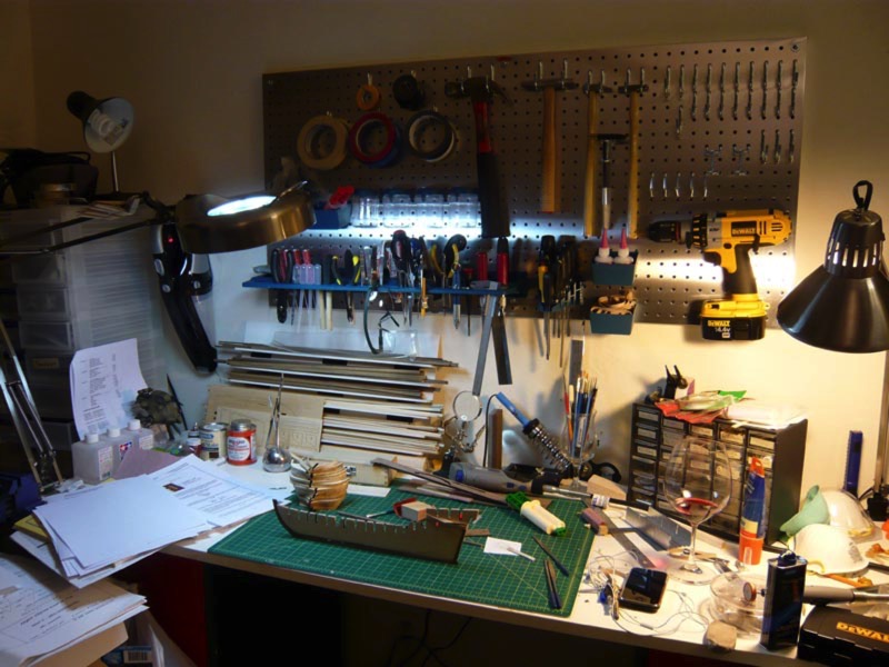
Then, the more complicated stuff: The ships wheel, the water pumps and the binnacle. The ships wheel and pumps seems fairly self evident, but if you are like me, you probably thought something like, "Binnacle? Is that like a barnacle? Perhaps the pinnacle of all barnacles, a sort of super-barnacle?" Turns out a binnacle is that little cabinet thing in front of the ships wheel that houses, among other things, the ships compass, which is supposed to be behind the little window.
The only noteworthy thing here is that I tried out using my drill as a makeshift lathe in order to turn a dowel into a pulley for the ships wheel (left side, where the string loops around). It seems to have worked decently, but I wouldn't recommend it for precision work.
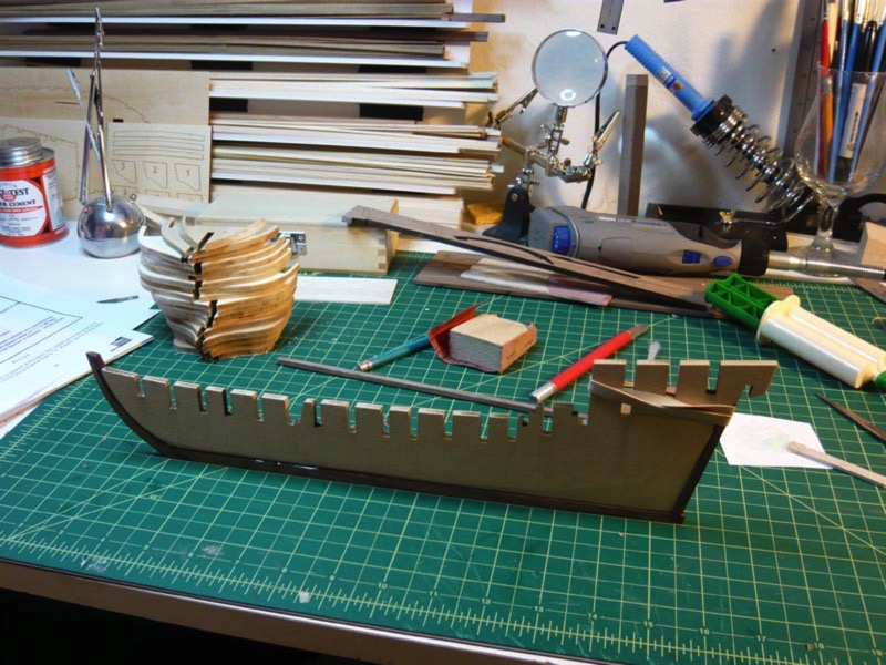
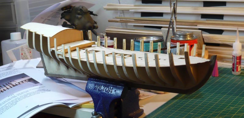
That's where I am now. More updates to follow as I progress!
(very exciting, I know)
In the next photo, you can see the smokestack for the galley, the riding bitt (little rope rack thing in the left-middle, there) and the catheads (little arms that stick off the front. No cats harmed in the making of this model).
Then, the more complicated stuff: The ships wheel, the water pumps and the binnacle. The ships wheel and pumps seems fairly self evident, but if you are like me, you probably thought something like, "Binnacle? Is that like a barnacle? Perhaps the pinnacle of all barnacles, a sort of super-barnacle?" Turns out a binnacle is that little cabinet thing in front of the ships wheel that houses, among other things, the ships compass, which is supposed to be behind the little window.
The only noteworthy thing here is that I tried out using my drill as a makeshift lathe in order to turn a dowel into a pulley for the ships wheel (left side, where the string loops around). It seems to have worked decently, but I wouldn't recommend it for precision work.
That's where I am now. More updates to follow as I progress!
Armed Virginia Sloop - Now Armed!
02 - September - 2009 - 21:48
First off, I've gotten the rudder attached. This wasn't too tough, but I thought that I would share a little trick I used. The course I am following didn't make any mention of the little bolt heads that secure the straps to the rudder and to the ship. The plans make a brief mention of using cut off bits of wire for these bolt heads. I figured that even if I managed to cut off that small of a piece of wire without it flying across the room and disappearing, then trying to get that tiny bit super glued to the rudder was going to be practically impossible. So, instead, I borrowed a jar of acrylic medium (thick), and dipped a T pin into it and dabbed little bits of the gel onto the metal straps. This left nice little dots on there, which were just the right size. Once dry, a little brush with fine sandpaper to take the points off the dabs, and then I painted over both the metal strap and the gel and it all turned out pretty well, if I may say so.
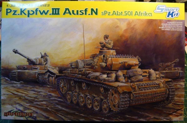
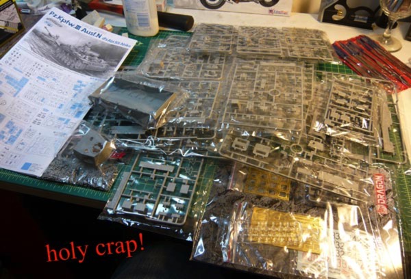
Once the rudder was all done, I set about rigging, and attaching the cannons to the ship. The rigging was extra fiddly, as it required some very small knots be tied and some fairly springy rope be coiled. I am now proud to say that I can precisely tie an hangman's knot that is only a few millimeters long. Should anyone need to hang any traitorous insects, I can be of assistance.
This step had one goof and one trick.
The goof: turns out I rigged the cannons backwards when it came to the little block-and-tackle things on the sides. The blocks with two holes were supposed to be towards the outside of the ship, resulting in the rope exiting the rigging near the railing of the ship and making much more sense, if you think about how one would haul on the rope to run the cannon out. But since I didn't discover this until I had already rigged all the cannons, I decided it wasn't too big a deal.
The trick: The course I am following suggested forming the rope coils (on the deck next to each cannon) by soaking the string in a mixture of Elmer's glue and water and then then using a wet paintbrush to form the ring of rope. I think my string may have been a different type (polyester instead of cotton), since it didn't really seem to soak up the glue mixture and become more pliable. Instead it mostly just spread glue all around the deck of the ship as I tried to get it to stay in place. Eventually, I gave up on that method and decided to instead form the coils by wrapping the string around the handle of a paintbrush (carefully overlapping, so that it built up some thickness and held itself in place) and the putting a dab of superglue (fast) on at the end to hold the coil together. Then, before the glue complete hardened, I slipped the coil off the brush handle and glued it down to the deck with another dab of superglue (slow). This seemed to do the trick, and aside from gluing my fingers together and to the rope a few times, it turned out pretty well.
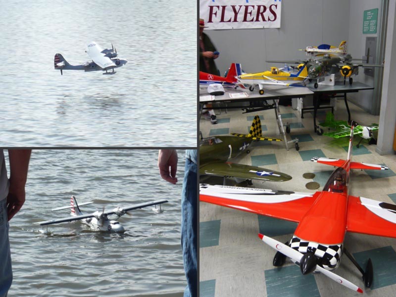
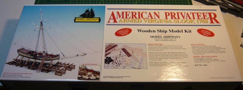
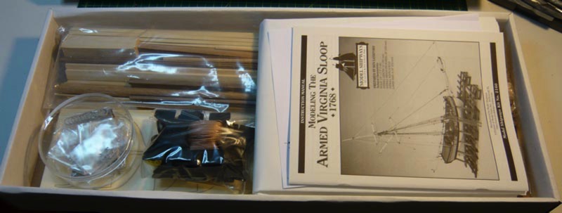
That's it for now. Next up are a few more pieces of random deck furniture, the little railing guns and various rigging fittings.
Once the rudder was all done, I set about rigging, and attaching the cannons to the ship. The rigging was extra fiddly, as it required some very small knots be tied and some fairly springy rope be coiled. I am now proud to say that I can precisely tie an hangman's knot that is only a few millimeters long. Should anyone need to hang any traitorous insects, I can be of assistance.
This step had one goof and one trick.
The goof: turns out I rigged the cannons backwards when it came to the little block-and-tackle things on the sides. The blocks with two holes were supposed to be towards the outside of the ship, resulting in the rope exiting the rigging near the railing of the ship and making much more sense, if you think about how one would haul on the rope to run the cannon out. But since I didn't discover this until I had already rigged all the cannons, I decided it wasn't too big a deal.
The trick: The course I am following suggested forming the rope coils (on the deck next to each cannon) by soaking the string in a mixture of Elmer's glue and water and then then using a wet paintbrush to form the ring of rope. I think my string may have been a different type (polyester instead of cotton), since it didn't really seem to soak up the glue mixture and become more pliable. Instead it mostly just spread glue all around the deck of the ship as I tried to get it to stay in place. Eventually, I gave up on that method and decided to instead form the coils by wrapping the string around the handle of a paintbrush (carefully overlapping, so that it built up some thickness and held itself in place) and the putting a dab of superglue (fast) on at the end to hold the coil together. Then, before the glue complete hardened, I slipped the coil off the brush handle and glued it down to the deck with another dab of superglue (slow). This seemed to do the trick, and aside from gluing my fingers together and to the rope a few times, it turned out pretty well.
That's it for now. Next up are a few more pieces of random deck furniture, the little railing guns and various rigging fittings.
Armed Virginia Sloop - quick update
16 - August - 2009 - 21:43
After a few weeks of turmoil, I'm beginning to get a bit of time here and there to work on the models again. This update shows the completed (sorta) cannons and the beginnings of the rudder. I added the 'sorta' to the cannons, as they still have a good deal of rigging work that will be done later in order to actually attach them to the ship itself. The rudder I just started today and should go pretty quick, since it is just a bit of simple sanding, carving and then cutting some bits of metal.
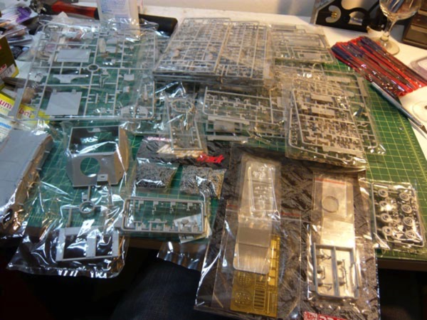
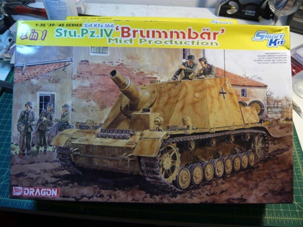
Armed Virginia Sloop - All Decking Complete
26 - July - 2009 - 20:44
Just a quick update to show the completed decking. At long last all the of frame and structure of the ship is covered. The next step is to start building the cannons, but I've got lots going on over the next week or two, so there may not be a worthwhile update here for a few weeks :)
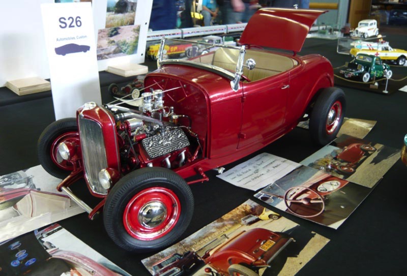
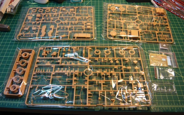
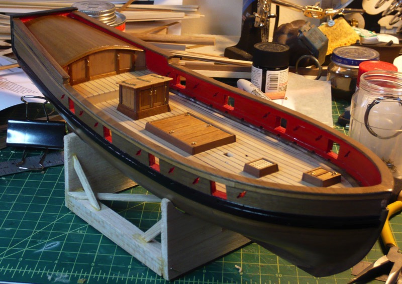
Armed Virginia Sloop - Decking
19 - July - 2009 - 19:40
Just a few images here of the in-progress deck planking. The main decking is done, and is soon to be followed by the mid deck planking. The black lines between planks here are meant to simulate the tar that was used on ships to waterproof the deck. In my model I just used a sharpie to color the edges of the planks before assembling them :) The various deck items from the previous post are shown below, although they are not actually glued into place yet.
Armed Virginia Sloop - Deck Objects
05 - July - 2009 - 20:45
A few days of cutting, sanding and gluing has brought forth an assortment of tiny little items:
There is a penny in the photo for size comparison, but needless to say, I had to learn to use two pairs of tweezers simultaneously in combination with a magnifying lamp. The grating on the smallest bit was assembled from some machine-cut comb-looking parts, so wasn't quite as tricky as it may look. I'm pretty happy with how the various brass bits turned out, although I found it quite difficult to satisfactorily file the ends of the brass wire that was used to simulate hinge pins. The files that I have are simply too coarse to smooth the ends of the wire, which get sort of smashed down by the wire cutters.
These are all of the deck buildings, though, so next step is main deck planking, and then cannons!
Armed Virginia Sloop - Planking Complete
03 - July - 2009 - 16:54
I've wrapped up the hull planking at long last. All in all, it was not too difficult overall, once I understood what the general goals were. It was a bit tedious, after a while, but I think the end result is very pleasing. Here are a few images of the unsanded and unfinished planking. In the second image, you can see where I goofed the planking pattern a bit.
Next I spent some time sanding the planking all smooth, starting with 150-grit sandpaper and then moving to 280 and then 320. Then, a coat of sanding sealer, some more sanding, and finally three coats of satin polyurethane.
Today, I spent time drilling and cutting and sanding the oar sweeps (diagonal holes in the sides). These were a little tricky, since the center hole is only 3/32" and I had to resort to the tiny bits (#62, I think) to drill through for the diagonal parts. Once the holes were drilled, I cut in between the holes with a tiny saw, and then made a thin sanding strip with some planking glued to sandpaper. I used that little sander to even out the interior of the holes. Then I painted the interior of each hole red, and then put polyurethane over everything that got painted or sanded, in order to have a nice uniform finish over everything. Finally, I decided to built a quick little working stand for the ship, since most of the work from this point on it on the deck. I just cut up some balsa that I had laying about and built a little stand, using the dremel to quickly get the stand to conform to the shape of the hull. There are some little felt circles in between the stand and hull, to avoid scrapes over time.
The kit comes with wood to build a stand, but since that wood is basswood, I was a little wary of building that stand now, since I think the basswood would get pretty beat up over time. I figure that this little balsa stand should do the trick for the time being and I don't have to worry too much about it getting broken. Anyhow, this is where the model stands at the moment:
Armed Virginia Sloop - continued
28 - June - 2009 - 21:53
I've been steadily plugging away on this model, mostly on planking-related tasks. I decided to do a little bit of painting, somewhat for accent/contrast, and somewhat to cover areas that would look bad if not painted (inside the gunports).
Here you can see the insides of the railing things painted the appropriate red color. I discovered, once I had the sides built up and the railings installed, that the back deck sides on my model were a bit taller than they are supposed to be. This meant that the sides up there, on my model, were only as thick as the outside basswood planking and looked pretty weird. So I spent a bit of time adding a few layers of wood to give those back walls thickness. It seems to have turned out okay, and I'm hoping it won't cause any issues later on in the build.
Once that was complete, I moved on to installing some of the main thicker planks on the upper outside of the hull and then adding the thin walnut finish planking to the upper areas.
From that point it was just a matter of planking the rest of the lower hull. It took me a little while to get the hang of how things go, but this task isn't too tough. It does get a bit tedious though, since it is really just a great deal of measuring and trimming plank after plank. Below you can see some of the masking tape guidelines that I used in order to help me control the flow of the planks around the hull.
I found that once I masked off a new line (based off of plank width), I could then go back and eyeball rough divisions of the intermediate space. So, for example, if the space between the tape and the finished planks required five full-width planks to cover it at the widest spot, then I would then move along the length of the ship and make marks that divided the space into five sections. If I did this every two inches or so, I found that I could then simply lay down an uncut 4" plank, see where it needed to be width-wise and then trim as needed. Then it was just a simple matter of cutting, gluing and, in some cases, soaking and bending, all of the planks required to fill the space. To the right, you can see the hull, a bit further along, with the markings for the last section in place.
That said, I discovered today that I still managed to goof up the planking on one side of the hull. It's nothing too major, but my planking pattern is off on every third plank, so that instead of a nice even distribution of plank ends, they are a bit offset. Since I was already about two thirds of the way done on that side, I decided I could live with it :)
Finally, here is where I stand at the moment. One side of the hull is planked, and the other side is about two thirds of the way complete. Once I finish the other side, I'll sand it all smooth, and then hit it with some sanding sealer, and polyurethane. Once I am happy with the exterior finish, it'll be time to move on to constructing some of the deck structures. I will be quite happy to be able to take a break from planking at that point (I'll still have to plank the main deck later). Overall, I am very happy with how things are progressing, although it seems that, when I ordered this kit in the first place, I grossly underestimated the amount of time required to complete it. At this rate, I'll be lucky if I have completed the kit before a year has elapsed since the kit first came into my possession. But it is a fun project and definitely the challenge I was hoping for!
Armed Virginia Sloop, pt 6
14 - June - 2009 - 20:18
Construction Continues.... The past few weeks have been super busy, and I've only just this weekend been able to devote some time to working on the ship.
Here you can see the ship all clamped up as I was gluing in the little basswood blocks where the sweep ports (oar-holes) go. Once that was all done, I found that I had to shim some of the ribs in order to get a uniform thickness everywhere. So, I spent some time shimming and trimming and sanding and cutting, and once satisfied, I was able to put the walnut planking on the inside.
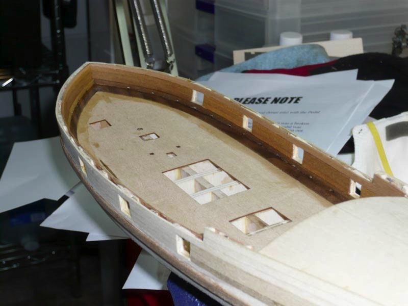
Here you can see the ship all clamped up as I was gluing in the little basswood blocks where the sweep ports (oar-holes) go. Once that was all done, I found that I had to shim some of the ribs in order to get a uniform thickness everywhere. So, I spent some time shimming and trimming and sanding and cutting, and once satisfied, I was able to put the walnut planking on the inside.
AVS Update (finally)
24 - May - 2009 - 22:00
So, at long last, I am finally updating the blog on the progress of the Armed Virginia Sloop.
I have been make slow but steady progress on the ship over the past two months, and more recently I've tried to increase my pace a little bit, as I was getting discouraged by the lack of visible progress. Currently, I have finished the first layer of exterior planking on the hull and am just beginning the walnut layer on both the inside of the rails and on the outside. Here are some images from the past two months and a little bit about them:
This first one shows the installation of the waterways, which I had been hung up on for a while. These were fairly thick, laser-cut, walnut parts that required a pretty big bevel along their length. Since I thought this was going to be tricky to get right, I had stalled for a while on it (plus I was pretty busy in outside life as well). But, once I got down to it, it turned out to not be that big a deal and I only cut myself a few times with the x-acto knife ;)
This next image shows the rear cabiny thing pretty much all done. This was actually a multi-step process, consisting of first planking in basswood. This first step was my introduction to planking with soaked wood (for added flexibility), which turned out to be quite handy. Once the area was planked with the basswood, it got a good sanding, and then the window frames were installed. I had some left over window plastic from the last boat I built (the Chris Craft at the bottom), so I cut some small squares from that and glued those to the backs of all the window frames with some Testors clear parts cement. Next, the area was given a final planking with the walnut layer, which required some delicate cutting and fitting around the frame areas. To finish it off, the surface was sanded smooth and given a light coat of polyurethane to seal it up a bit.
Here is another view of the cabin area. You can also see the first few planks going on the side. This mostly involved a process of roughly measuring the planks, then soaking them in water for a bit, then attaching them with super glue. Once the wood had dried out a bit, things are trimmed and sanded to fit nicely.
There is a bit of a trick to this whole stern area, as many of the bits sort of rely on one another for positioning. The course that I am following (see link in sidebar) does a good job of differing from the kits instructions in order to make these interrelationships obvious. As a result, it sort of skips back and forth for a bit, adding a few planks, then some trim pieces, then more planks, etc.
Here is an image of the walnut trim corner pieces in place. These interact with the installed walnut planking, as well as the side planks in the way that it fits together. This step also required a bit of muscle (delicately) to bend my top rear planks out a bit. They had ended up curling in a bit, so that when i installed the straight trim pieces, they did not line up properly. With a little bit of super glue, some delicate but firm pressure, and some patience, I managed to bend the rear surface out a bit to align with the trim. This looked much better and generally filled life with happiness ;)
Skipping ahead a few weeks, the planking is well underway. This mostly involved steps of pinning, drawing guide lines along the planks, unpinning, careful cutting, soaking and then finally gluing in place, with a bit of trimming at one end for a proper fit. Not too tough, really, but pretty slow going. I think I averaged two to four planks on evenings that I was able to work on the ship. The image to the left is probably three to four weeks of slow work. Once I got this far though, I got excited about being almost done this stage, and pushed ahead a bit quicker. As a result, I am now all done with the basswood planking!
As you can see, in this image, The planking is complete and I've spent a bit of time sanding the whole hull and filling in a few gaps with green putty. Overall, I'm quite pleased with how it turned out
for being my first ship. There are a few areas that could be better (hence the need for the filler), but really nothing that is too bad. It was a bit tricky getting the planks to bend at the stern, as the planks were pretty wide (1/4") and the required bend was pretty extreme. But once all was sanded and filled, it seemed to work out just fine.
Next up is to begin the walnut planking on the interior of the railing. I believe this also involves a bit of cutting and fitting to a few pieces, but didn't look too complicated.
I'm hoping to be a little better about updates from here on, so keep an eye out for small posts as I progress!
Also, on a side note, be sure to go see Pixar's 'Up' this coming week, when it comes out! It's a great film!
Armed Virginia Sloop, pt4
24 - March - 2009 - 21:38
I haven't had much time recently to work on the ship, but I have managed to get the rear structure built and the front filler pieces cut and fit and sanded. Both ends took a good deal of shaping and sanding, and therefore took a bit longer than I was expecting.
I highly recommend getting a Dustbuster for your work area, if you don't already have one. I have found that having a little vacuum like that around allows me to really keep the amount of sawdust and wood shavings to a minimum. I'm hoping, in the long run, that this will save me a good deal of cleaning later. When I built the little speedboat (lower on the page), I ended up with a coating of fine sawdust all over everything in the room, which was a real task to clean up.
Here are a few photos of where I currently am. I am also goofing around with the picture layout thing. It's a bit clumsy to use.
Armed Virginia Sloop, pt3
15 - March - 2009 - 21:29
At long last I have an update for this build. I've managed to get most of the frame of the hull assembled. The actual assembly was pretty quick (it's easy to glue things together), but once things were assembled, there was a great deal of sanding and fitting to do to make life easier inlater steps. Apparently, this is called 'fairing' the hull. It mostly consists of taking a scrap strip of wood and laying it along the outside of the hull so that one can see which ribs stick up higher or are lower than the rest. Then one must sand down the high ribs or glue on strips of wood for the low ribs. Then there is more sanding, a bit of sneezing (turns out my nose doesn't like saw dust very much), then a bit more fitting and sanding. There is also a great deal of accidental breakage of tiny wood parts, followed by loud cursing and then some reglueing of those parts.
This is also where the course that I am following differs a bit from the instructions that come with the kit. The course had me attach the sub decking (just a thin sheet of basswood) before framing the rear cabin, in order to give strength to the whole ship. While the instructions suggested putting little support pieces between the ribs to give it strength, and doesn't have me put on the subdeck until after all the rest of the framing is done. I can appreciate that the course method saves me quite a bit of time that would have otherwise been spent cutting little blocks of wood, but I like to think I made up for it in time spent glueing pieces of that thin deck back on after I managed to break them off while working on a different part of the hull. ;-)
All in all, I think I've got the hull faired and am ready to move on to framing up the rear cabin of the ship. There is probably a better term for that part of a ship, but I can't remember it at the moment :)
Anyhoo, here are some photos of where I am now:
Armed Virginia Sloop, pt 2
03 - March - 2009 - 21:56
I've gotten a little start on the ship. Mostly some cutting, sanding and fitting. I cut out the keel, and all the bulkheads, sanded their edges, and sanded the joints a bit until they all fit together. I've also received the practicum course mentioned below, and have been reading and following that.
I did some cutting and beveling on the center keel and have just started to actually attach some pieces together. You can see below, I've glued the walnut keel pieces to the edges of the basswood center keel. Next comes more cutting and carving and fitting, as I need to be sure that the groove into which all the planking will later fit is the proper size and angle before all the bulkheads get glued in place.
On a side note, today I received the pegboard that I order a few weeks ago. So, I spent some time this evening organizing and generally pegging things up on my board. Really, the goal was just to get many of my tools up off the desk, giving me more work space.
This past weekend, I also spent a few minutes making myself a little foamcore shelf sort of thing that I could put all the plank wood on, to keep it out of the way and to keep it from getting broken. In the below photo, you can see the little shelf below the left side of the pegboard.
Next post will hopefully have the bulkheads in place, and the shape of the ship will actually be a bit more visible.
Model Shipways Armed Virginia Sloop
26 - February - 2009 - 20:49
So, my new kit arrived yesterday :-D
Just a little background: I chose this particular kit because the folks on the Drydock Models forums seemed to agree that this was one of a couple good starter boats. Reasons include good instructions, high kit quality, less scratch building, and the availability of kit-specific training materials.
As I mentioned in a previous post, the Lauck Street Shipyard has a very detailed course on building this kit. It goes into an enormous amount of detail and aims to teach many of the tricks of the trade in regards to model ship building. If you are curious, they have the first section of many of the courses available to download and check out for free.
So there is a little background, which brings us up to the new kit. I spent last night picking through the parts and making sure everything was accounted for. After an hour or two of counting parts and measuring wood stock, it seemed everything was in order. There was a tiny bit of damage to one of the very thin laser-cut deck sheets, but it was something that was easily glued back on. I re-glued it last night and it seems to be good as new today, but will take a little sanding once installed later.
I'm now waiting for some organizational items to arrive, to help get my workspace cleaned up a little, and I'm also waiting for the aforementioned building course to arrive. But in the mean time, I have gotten the first section of the course, through which I can read and begin a bit of work. I've also purchased "How to Build First Rate Ship Models From Kits" by Ben Lankford (available from modelexpo-online.com), which I'll be reading as well. All in all, I'm hoping to learn a great deal while building this ship, so that I need much less assistance on the next one.
The box:
The box..... opened!
After all the counting and sorting and such:
1930 Chris Craft Runabout in 1/24 scale
19 - February - 2009 - 21:15
Here are a few images of the last model I finished. This was the first model that I have ever done that had a finished wood construction. When I was a kid I had done a few of the little balsa airplanes that have a tissue out surface, but this boat was a totally different beast.
This kit is a Dumas Boats 1930 Chris Craft Runabout at 1/24 scale. The finished product is about 12" long. It's got a balsa frame and underplanking, with mahogany final planking.
Previous to this kit, almost all of the kits I have built have been plastic. This meant the emphasis was far and away on the painting and cleanup of the plastic. A little filler here, some shading and weathering there and the kits come out nice. This, on the other hand, was a good deal more about the construction, with hardly any painting at all. There was a great deal of shaping and sanding of the raw planks of wood, which, while making a saw-dusty mess of my office, made me feel much more like I had actually BUILT the model, rather than just assembled a kit. There was also a bit of metal cleanup and polishing on the white metal parts, and some working with materials I had not dealt with before (sheet adhesive aluminum).
Overall, I learned quite a bit and whet my appetite for further exploration into the ship building process. As a result, I decided to order up a new ship model (see previous post), with a good deal more complexity, and give that a try.
New model ordered, Model Expo 2009
19 - February - 2009 - 11:06
So I've ordered up a new model to start on: A Model Shipways 1:48 scale Armed Virginia Sloop. After finishing my first wooden model, I decided that I liked it, and that I should give something a little more complicated a try. I think I will also get the course on building this particular model from: http://www.lauckstreetshipyard.com Hopefully this will help me learn many of the tricks of the trade, without making a mess of things.
More info on the model, image source, etc can be had here:
http://www.modelexpo-online.com/product.asp?ITEMNO=MS2160
Also, this weekend is Hobby Expo 2009, up in Petaluma. I only just discovered this the other day, and having never been to one of these things myself, I figured I would go up and check it out. I'm hoping there will be someone there selling some of the Maschinen Krieger (sp?) kits, since they seem to be tricky to find these days.