
Plastic
Tamiya Ferrari Enzo
30 - August - 2015 - 18:22
After over a year of slacking on my blog, I’m back! Coinciding with a re-work of my web site and a move over from the blogspot location, I’m getting this blog moving again with a few new projects. I’ll touch on the second project in later posts, but for now, let’s have a look at…
The 1/12 Tamiya Ferrari Enzo!
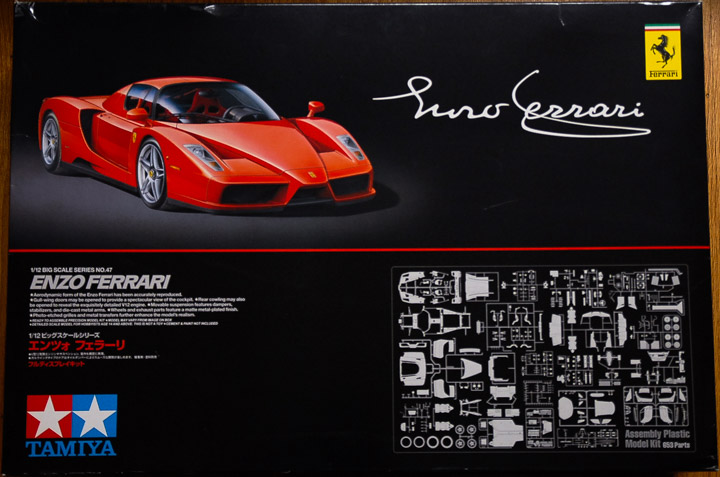
This kit is a monster, at 1/12 scale, with tons of detail and construction methods that mirror how the car is built at full scale. It’s got working, spring loaded doors, fully detailed engine and front trunk, working suspension and the molding is all top notch. Tamiya always does a great job with their kits and this one is no exception.
I also am calling upon some great resources from Scale Motorsport on this project. They offer a handy dvd full of reference photos of the Enzo, which allow me to pick through photos of the real thing and see which things the kit is missing and what details should be added.
But, as anyone who has followed a few of my projects knows, I’m never one to leave well enough alone. I couldn’t help but try to make this great kit even better. Scale Motorsport makes a few sets of extra parts for this kit that make it even more detailed.
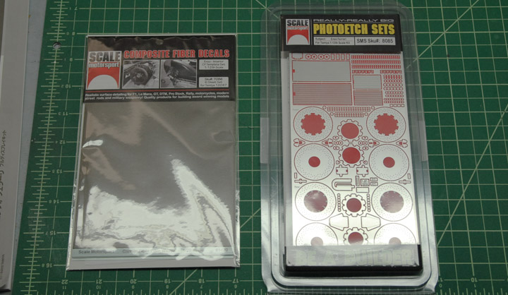
They offer a giant set of photo etch parts that add detail in some places, replace molded details in other places and generally make things look nicer. They also offer some great carbon fiber decal sets that are designed for this kit. I purchased the kit that covers the interior surfaces of the car that are unpainted carbon fiber on the real car.
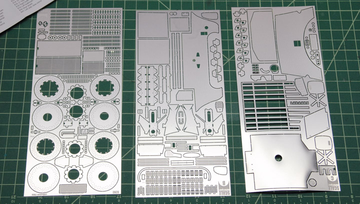
Below you can see the photo etch sheets, which are quite large.
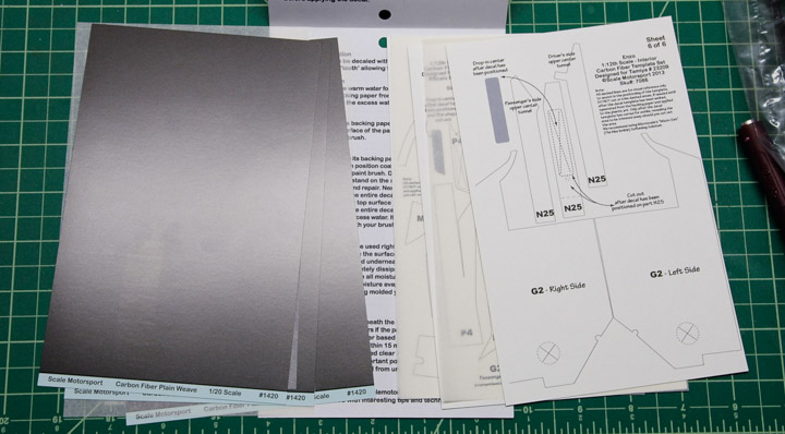
Below you can see the sheets of composite decals. On the back of each sheet are the cut lines for each piece along with the part number that they are to go on to.
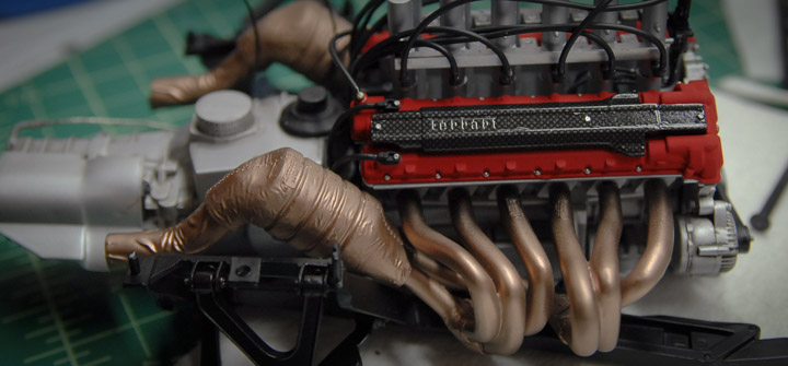
The first step in construction is the engine. At 1/12 scale, the engine is pretty huge. The big benefit here is that the parts are large, easy to work with and the detail well defined. This also presented the first opportunity to use some of the photo etch parts.
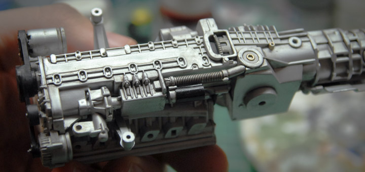
Below you can see the painted engine block with a quick dirt wash on it to help pick out the details.
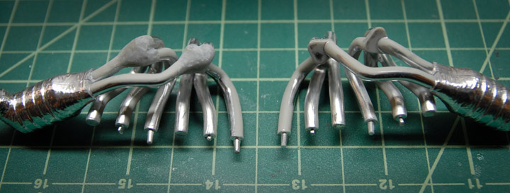
In picking through the reference photos, I noticed that the headers didn’t end in a flat plate like the plastic parts do, but had smooth 3-to-1 collectors. I decided that this was something that I needed to change. Using some Milliput epoxy putty, I formed some transitions, let them harden and then ground them into final shape. Below you can see the headers with and without the putty in place.
Part of the photo etch upgrade kit are these little plates that attach to the headers and catalytic converter.
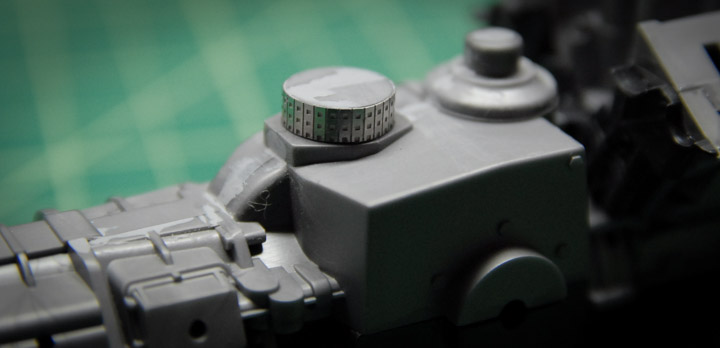
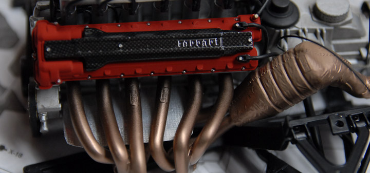
Below you can see the engine coming together and starting to look more engine-y. The valve cover piece was not part of the composite decal kit, but I order a few extra sheets of the decal so that I could add it in a few places. This one took quite a bit of fitting, cutting and adjusting to get it mostly conformed to the part. A healthy dose of decal softener and some clear coat got it looking pretty good.
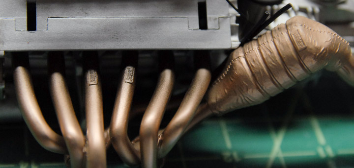
I noticed in the reference photos that on the real car, there was a heat shield underneath the headers, presumably to help keep heat away from the oil pan (?). Whatever they are for, there was no corresponding part either in the kit or in the additional photo etch, so I made something out of some things I had in my extras drawer. I had some of the thin aluminum that was left over from the Curtiss Jenny model, cut out a piece of the appropriate size and then, because the real part has some pattern stamped into it, I used a little piece of screen (from a faucet) to hammer some pattern into my piece.
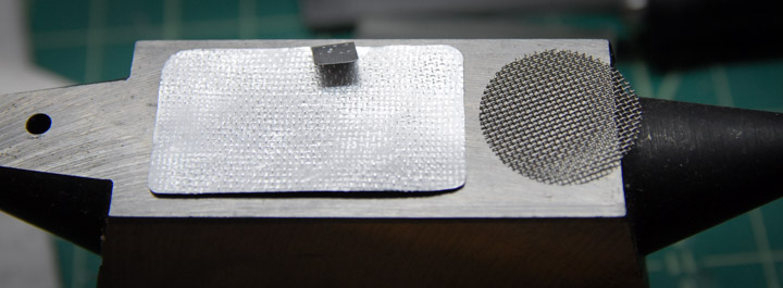
Below you can see the part installed.
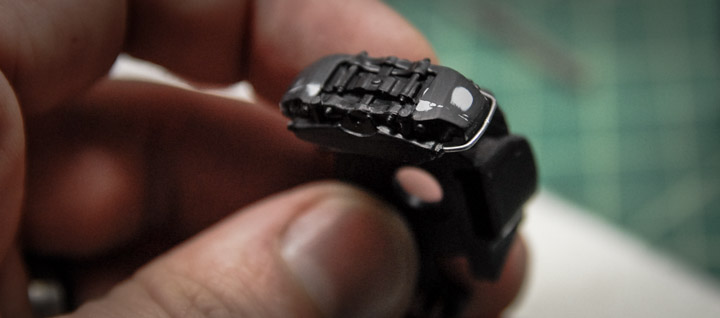
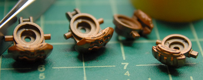
Next, construction moved to the drive train that is connected directly to the engine. This began with the brake assemblies. The photo etch kit had some replacement parts here. It had me sand the kit discs smooth and then put an outer disc, hub and bolts on in order to better represent the multi-piece rotors on the real car.
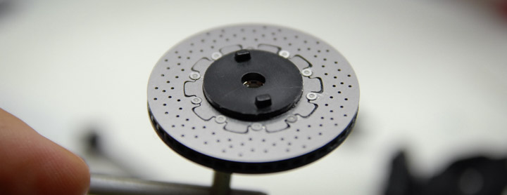
Looking at the reference, I thought that the brake calipers could be improved upon a bit, since the little tube that connects the two calipers was molded onto the plastic and wasn’t very convincing. I sanded that one off and replaced it with a bit of solder, in order to better mimic the real car.
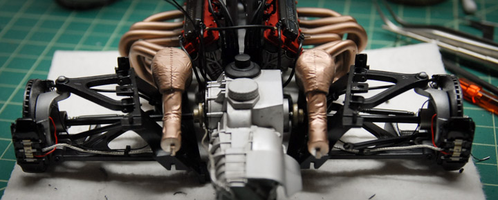
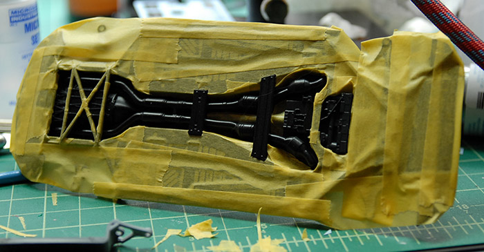
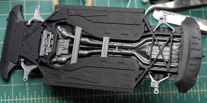
As the hubs and rear suspension came together, I tried to add in some of the plumbing that wasn’t added by the kit. In some cases, the kit did supply some plastic tubing to be used for brake lines. Those that have put together a Tamiya kit before will be familiar with the hollow tubing that they generally supply. It usually looks very nice, but can be tricky to work with, since it is very light weight and a bit springy. This just makes it difficult to get the tubes to stay right where you want them to be. My trick with these tubes is to carefully run a bit of solder through the tube that is just small enough to fit through. The weight of the solder helps the tubes act a little more like the real things and the solder also allows me to bend and shape the tube as I see fit. Below you can see the solder sticking out of the end of the tubes before I added them to the model.
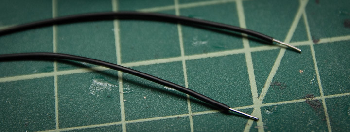
Below you can see the rear assembly and some of the tubes that have been added.
Next, assembly moved to the front trunk area. The kit includes the visible parts of the trunk, as well as the various electronics that go underneath the trunk. The trunk itself is removable, should you want to show off the details. After checking the reference, I decided I wanted some more wires under there, so I put together a simple wiring harness to tie into the various boxes. Below you can see the wires before they are installed.
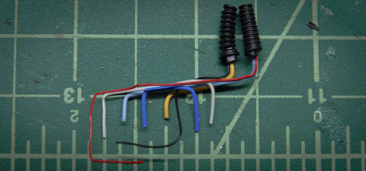
Here they are in place. I also used some black tissue paper, dampened with a white glue and water mixture, to simulate the cloth wrap that is used around the real wires.
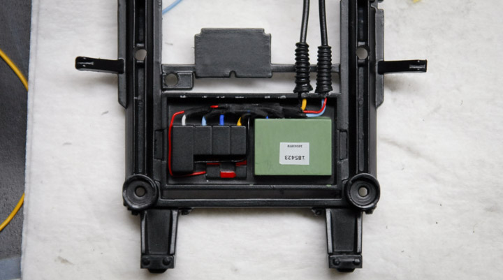
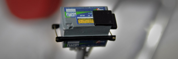
The battery didn’t have any decals with the kit, so I tracked down the brand that the car uses, and made a few decals of my own. I also fabricated an approximation of the little bracket that holds the battery in place.
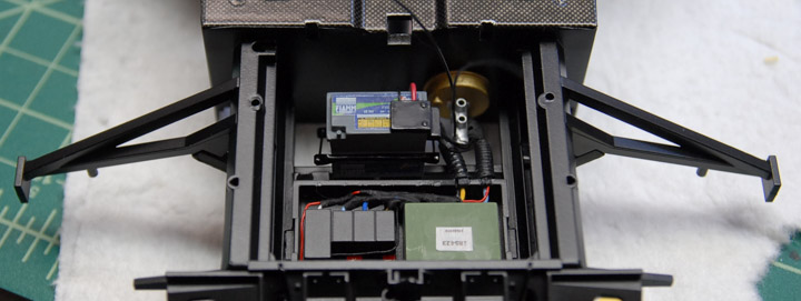
Here you can see everything in place in between where the front wheels will be.
That’s all for now. Construction has moved on a bit further, so look for another post soon, with the front suspension construction and some difficulties with the photo etch on the muffler. Thanks for reading!
The 1/12 Tamiya Ferrari Enzo!
This kit is a monster, at 1/12 scale, with tons of detail and construction methods that mirror how the car is built at full scale. It’s got working, spring loaded doors, fully detailed engine and front trunk, working suspension and the molding is all top notch. Tamiya always does a great job with their kits and this one is no exception.
I also am calling upon some great resources from Scale Motorsport on this project. They offer a handy dvd full of reference photos of the Enzo, which allow me to pick through photos of the real thing and see which things the kit is missing and what details should be added.
But, as anyone who has followed a few of my projects knows, I’m never one to leave well enough alone. I couldn’t help but try to make this great kit even better. Scale Motorsport makes a few sets of extra parts for this kit that make it even more detailed.
They offer a giant set of photo etch parts that add detail in some places, replace molded details in other places and generally make things look nicer. They also offer some great carbon fiber decal sets that are designed for this kit. I purchased the kit that covers the interior surfaces of the car that are unpainted carbon fiber on the real car.
Below you can see the photo etch sheets, which are quite large.
Below you can see the sheets of composite decals. On the back of each sheet are the cut lines for each piece along with the part number that they are to go on to.
The first step in construction is the engine. At 1/12 scale, the engine is pretty huge. The big benefit here is that the parts are large, easy to work with and the detail well defined. This also presented the first opportunity to use some of the photo etch parts.
Below you can see the painted engine block with a quick dirt wash on it to help pick out the details.
In picking through the reference photos, I noticed that the headers didn’t end in a flat plate like the plastic parts do, but had smooth 3-to-1 collectors. I decided that this was something that I needed to change. Using some Milliput epoxy putty, I formed some transitions, let them harden and then ground them into final shape. Below you can see the headers with and without the putty in place.
Part of the photo etch upgrade kit are these little plates that attach to the headers and catalytic converter.
Below you can see the engine coming together and starting to look more engine-y. The valve cover piece was not part of the composite decal kit, but I order a few extra sheets of the decal so that I could add it in a few places. This one took quite a bit of fitting, cutting and adjusting to get it mostly conformed to the part. A healthy dose of decal softener and some clear coat got it looking pretty good.
I noticed in the reference photos that on the real car, there was a heat shield underneath the headers, presumably to help keep heat away from the oil pan (?). Whatever they are for, there was no corresponding part either in the kit or in the additional photo etch, so I made something out of some things I had in my extras drawer. I had some of the thin aluminum that was left over from the Curtiss Jenny model, cut out a piece of the appropriate size and then, because the real part has some pattern stamped into it, I used a little piece of screen (from a faucet) to hammer some pattern into my piece.
Below you can see the part installed.
Next, construction moved to the drive train that is connected directly to the engine. This began with the brake assemblies. The photo etch kit had some replacement parts here. It had me sand the kit discs smooth and then put an outer disc, hub and bolts on in order to better represent the multi-piece rotors on the real car.
Looking at the reference, I thought that the brake calipers could be improved upon a bit, since the little tube that connects the two calipers was molded onto the plastic and wasn’t very convincing. I sanded that one off and replaced it with a bit of solder, in order to better mimic the real car.
As the hubs and rear suspension came together, I tried to add in some of the plumbing that wasn’t added by the kit. In some cases, the kit did supply some plastic tubing to be used for brake lines. Those that have put together a Tamiya kit before will be familiar with the hollow tubing that they generally supply. It usually looks very nice, but can be tricky to work with, since it is very light weight and a bit springy. This just makes it difficult to get the tubes to stay right where you want them to be. My trick with these tubes is to carefully run a bit of solder through the tube that is just small enough to fit through. The weight of the solder helps the tubes act a little more like the real things and the solder also allows me to bend and shape the tube as I see fit. Below you can see the solder sticking out of the end of the tubes before I added them to the model.
Below you can see the rear assembly and some of the tubes that have been added.
Next, assembly moved to the front trunk area. The kit includes the visible parts of the trunk, as well as the various electronics that go underneath the trunk. The trunk itself is removable, should you want to show off the details. After checking the reference, I decided I wanted some more wires under there, so I put together a simple wiring harness to tie into the various boxes. Below you can see the wires before they are installed.
Here they are in place. I also used some black tissue paper, dampened with a white glue and water mixture, to simulate the cloth wrap that is used around the real wires.
The battery didn’t have any decals with the kit, so I tracked down the brand that the car uses, and made a few decals of my own. I also fabricated an approximation of the little bracket that holds the battery in place.
Here you can see everything in place in between where the front wheels will be.
That’s all for now. Construction has moved on a bit further, so look for another post soon, with the front suspension construction and some difficulties with the photo etch on the muffler. Thanks for reading!
Completed: Morgan Three Wheeler
05 - January - 2014 - 14:55
In the last post, I mentioned converting this model from an air-cooled engine to a water-cooled one.
When I began the project, I did my usual reference hunting on the internet. I pulled together a couple dozen images, made myself a printout of a collection of those and got to work. After a little while, I started to find large discrepancies between the model kit and my reference images. What I discovered was that there are a few different engines that all seemed to be used around the same time (mid 1930's). Of those, two were made by Matchless, one of which was air cooled. The differentiating features of the air-cooled engine are the fins on the cylinders and the smaller opening on the cowl behind the engine.

The other Matchless engine was water cooled, which can be spotted by the smooth cylinders, larger cowl opening and pipes going from the tops of the cylinders to the radiator inside the cowl.
The kit had an air-cooled engine, but, like many other parts on this kit, it wasn't a very good rendition. The detail was largely obscured by extra flash and poor mold alignment, even after all of the chrome was stripped off. Aside from that, I really just liked the way that the water cooled engine looked better. So, I decided to make a replacement engine.
I'd been toying with the idea of making model parts in the computer and then having them 3d printed, and this was the perfect opportunity to try it out. This presented a good test case for a number of reasons. First off, this engine is not very big, so many of the details on the engine are on the tiny side of what 3d printers can handle. This meant that I could see how well the details are reproduced when it gets down to the limits of the printers. Also, this let me get the same part printed in two different materials, to see if the higher-detail material was worth the extra cost (spoiler: it was).
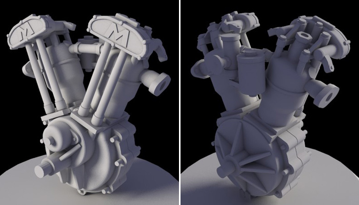
So that said, I fired up trusty ol 3dsmax, and modeled up an engine that was sized to fit in place of the kit engine. This took a bit of quality time with the assembled kit engine, some calipers, and lots of careful measuring. What you see below is what I came up with and sent to Shapeways for printing. I sent them two files, one for the engine and one for the radiator.
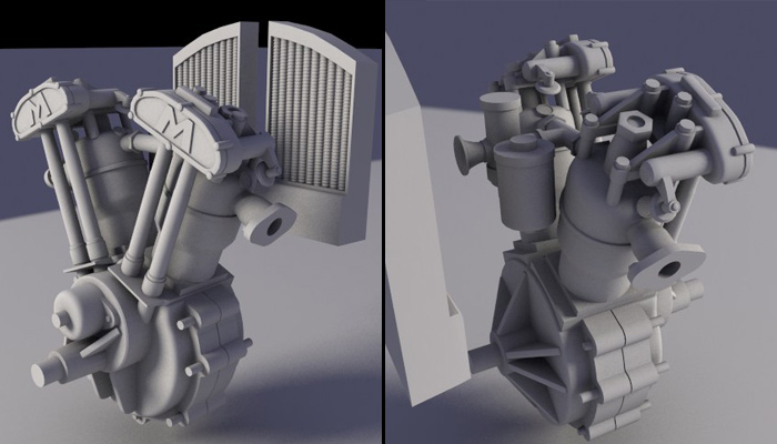
The radiator worked just fine and moved from prep to printing pretty quickly. The engine, on the other hand, got kicked back to me for various reasons. Mostly, it was because of various areas being too thin. Instead of them just trying to print whatever you send them (which is what I thought they would do), they check the file first and let you know if there are any areas that could cause trouble. After a few go-arounds with that process I ended up with the engine model you see below. It has many of the thin bits thickened up, and the valve spring cap things removed entirely.
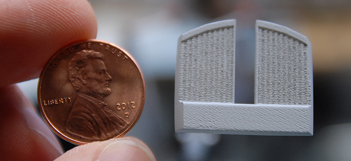
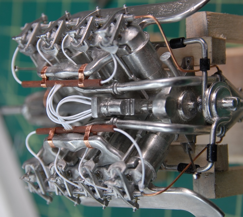
So, while the engine was being printed, the new radiator arrived! What you see below is my first 3d printed model part, cleaned and primed, next to a penny for scale.
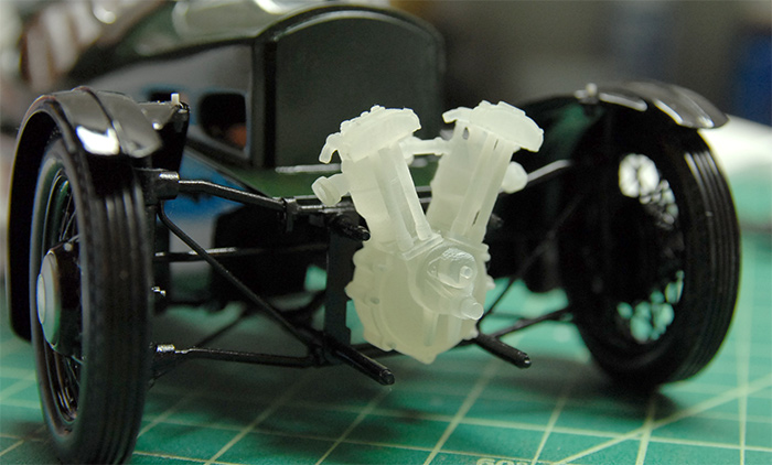
A few weeks later, the 3d printed engine arrived and below you can see my first test fitting, as well as what the raw printed material looks like.
While the initial test fitting went pretty well, later fittings caused a little bit more trouble, as there were quite a few things to get aligned all at once. In the end, I ended up replacing some of the pins that were printed with the engine (the ones that go through the chrome plates) with small brass rod, for durability and so that I could reposition them slightly. Below you can see the final fitting, with radiator piping, made of brass rod and heat-shrink tubing, in place.
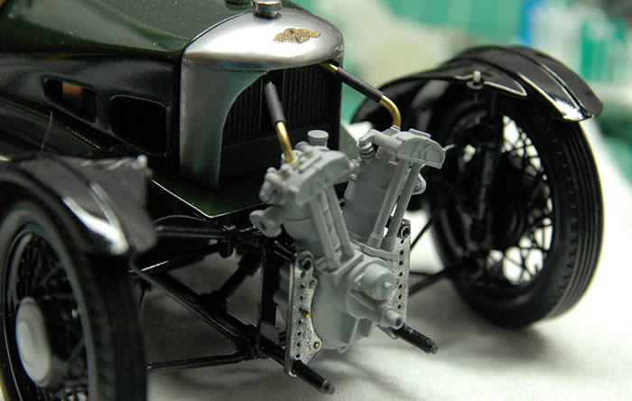
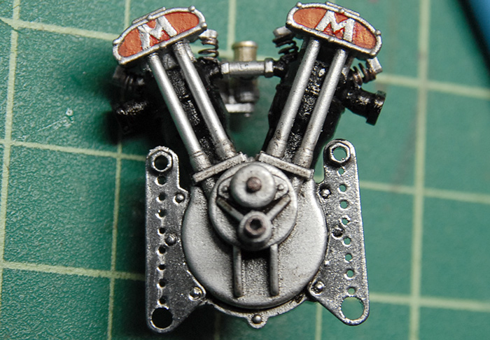
Once I was sure everything would fit, it was time for paint. Below you can see the painted engine, with some valve springs made from wound wire and the front frame plates attached.
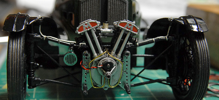
And finally, the finished engine, in place, along with some plumbing (although the radiator pipes are not glued on in this photo), ignition wiring and some wiring to where the headlights will go.
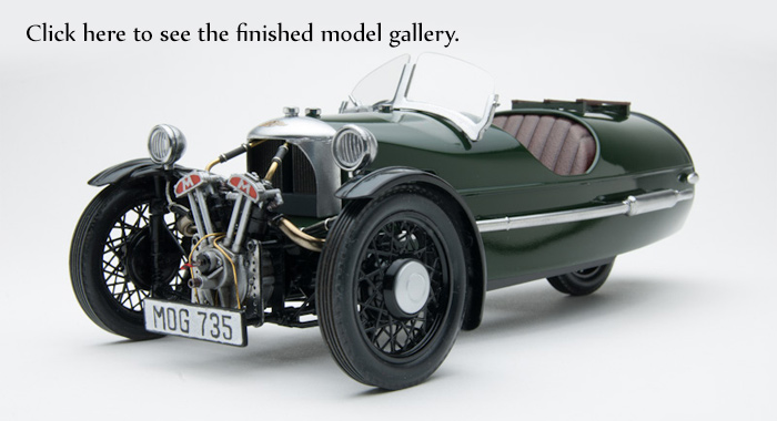
Overall, this was an informative project, and a good test for the 3d printing. Click on the image below to go to the galley of photos of the finished model:
Next up for me is some practice with car paint finishes.
I've also got something bigger in the works, which I'll reveal here once it's a bit closer to being ready ;)
Thanks for reading!
When I began the project, I did my usual reference hunting on the internet. I pulled together a couple dozen images, made myself a printout of a collection of those and got to work. After a little while, I started to find large discrepancies between the model kit and my reference images. What I discovered was that there are a few different engines that all seemed to be used around the same time (mid 1930's). Of those, two were made by Matchless, one of which was air cooled. The differentiating features of the air-cooled engine are the fins on the cylinders and the smaller opening on the cowl behind the engine.
The other Matchless engine was water cooled, which can be spotted by the smooth cylinders, larger cowl opening and pipes going from the tops of the cylinders to the radiator inside the cowl.
The kit had an air-cooled engine, but, like many other parts on this kit, it wasn't a very good rendition. The detail was largely obscured by extra flash and poor mold alignment, even after all of the chrome was stripped off. Aside from that, I really just liked the way that the water cooled engine looked better. So, I decided to make a replacement engine.
I'd been toying with the idea of making model parts in the computer and then having them 3d printed, and this was the perfect opportunity to try it out. This presented a good test case for a number of reasons. First off, this engine is not very big, so many of the details on the engine are on the tiny side of what 3d printers can handle. This meant that I could see how well the details are reproduced when it gets down to the limits of the printers. Also, this let me get the same part printed in two different materials, to see if the higher-detail material was worth the extra cost (spoiler: it was).
So that said, I fired up trusty ol 3dsmax, and modeled up an engine that was sized to fit in place of the kit engine. This took a bit of quality time with the assembled kit engine, some calipers, and lots of careful measuring. What you see below is what I came up with and sent to Shapeways for printing. I sent them two files, one for the engine and one for the radiator.
The radiator worked just fine and moved from prep to printing pretty quickly. The engine, on the other hand, got kicked back to me for various reasons. Mostly, it was because of various areas being too thin. Instead of them just trying to print whatever you send them (which is what I thought they would do), they check the file first and let you know if there are any areas that could cause trouble. After a few go-arounds with that process I ended up with the engine model you see below. It has many of the thin bits thickened up, and the valve spring cap things removed entirely.
So, while the engine was being printed, the new radiator arrived! What you see below is my first 3d printed model part, cleaned and primed, next to a penny for scale.
A few weeks later, the 3d printed engine arrived and below you can see my first test fitting, as well as what the raw printed material looks like.
While the initial test fitting went pretty well, later fittings caused a little bit more trouble, as there were quite a few things to get aligned all at once. In the end, I ended up replacing some of the pins that were printed with the engine (the ones that go through the chrome plates) with small brass rod, for durability and so that I could reposition them slightly. Below you can see the final fitting, with radiator piping, made of brass rod and heat-shrink tubing, in place.
Once I was sure everything would fit, it was time for paint. Below you can see the painted engine, with some valve springs made from wound wire and the front frame plates attached.
And finally, the finished engine, in place, along with some plumbing (although the radiator pipes are not glued on in this photo), ignition wiring and some wiring to where the headlights will go.
Overall, this was an informative project, and a good test for the 3d printing. Click on the image below to go to the galley of photos of the finished model:
Next up for me is some practice with car paint finishes.
I've also got something bigger in the works, which I'll reveal here once it's a bit closer to being ready ;)
Thanks for reading!
Beginning the Build: Morgan Three Wheeler
01 - December - 2013 - 14:19
On my continuing quest for a better car paint finish, I've chosen a Morgan Three Wheeler model, from Minicraft, as my next build.
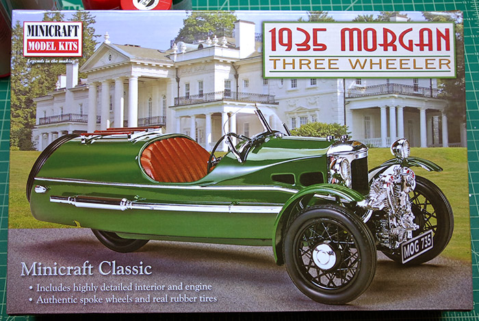
Often, when I pick out kits to build, I do so because of the difficulty and complexity of the kit. I look for well-engineered kits, with lots of extras like photo-etch, metal parts, great decals, etc. This kit, on the other hand, I picked out because I really like the Morgan Three Wheeler. I've seen a few in person and always though that they were just really cool vehicles.
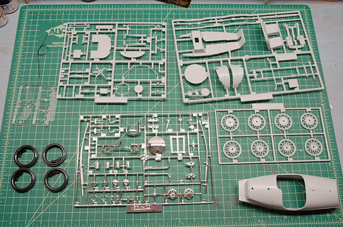
As a result of that method of kit selection, this one ended up taking quite a bit of extra work to make it acceptable. Below you can see the parts as they came out of the box: A few trees of a fairly soft grey plastic, some hard-ish rubber tires, some clear parts, a length of tubing for the engine and one tree of thickly-coated chrome parts.
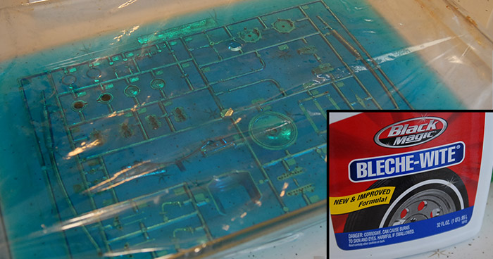
First and foremost, I knew that the chrome parts were just not going to cut it. The varnish/primer that they use under the chrome was on there pretty thick, and in combination with the chrome paint, was filling in many of the details on the parts. That's not evening mentioning the fundamental problem with parts that are painted on the trees: The spots that are left unpainted on the parts once they are cut off the sprue. I decided to give a technique a try that I had read about online and in magazines: de-chroming the parts with Bleche-wite. Bleche-wite is a cleaner that is meant to whiten the whitewalls of tires. It's a pretty aggressive cleaner, so should be handled with care, in a well-ventilated area. I used a baking dish, with the bottle of cleaner emptied into it. I dropped the chrome sprue in there and covered it with plastic wrap. I found that it took a couple multi-hour sessions to get all the chrome off, but because this solvent isn't as aggressive as something like lacquer thinner, I didn't have to worry about the plastic itself dissolving. If you are going to try this yourself, I recommend giving it a few hours in the cleaner and then giving it a light scrubbing with a toothbrush (don't use the brush afterward, despite the tooth-whitening potential), and repeat that process until all the chrome and underlying varnish is all gone.
With that out of the way, I should probably mention something about this kit: It is a mess. Compared to many of the other kits that I have built, from the likes of Tamiya, Hobbyboss and Dragon, this one is of markedly lower quality. There is heaps of flash, the registration between the mold halves is not very good, there are ejector pin marks and sinks all over the place and it just requires a great deal of work to get into shape.
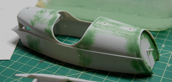
That said, I began by getting the body into a state that is ready for primer and paint. There were sinks on the exterior of the body in every place where there were structural braces on the inside. I ended up thinning some green Squadron putty with some lacquer thinner and spreading that over these areas. After that, I worked my way through various grits of sandpaper, wet sanding until it was smooth enough to be primed. Below you can see the exterior has been sanded, but the rear tire area still needs to be cleaned up.
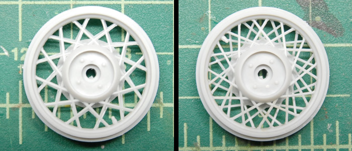
Also, while consulting some reference, I determined that the way the instructions wanted me to put the wheel halves together would have resulted in wheels that didn't really look like the real things. The 1:1 car's wire wheels look to have an offset pattern, making for a much more visually-dense criss-cross pattern. The way the parts aligned resulted in all the spokes lining up, making for a much simpler look. I wanted the more complex look, so I shaved off the locator pins and offset the halves a few degrees. Below you can see the stock and offset locations of the wheel halves.
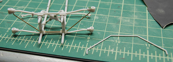
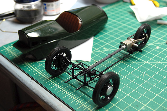
Some thing unusual about this kit is that it is constructed very much like the real car, with an underlying frame that the body sits on top of. While I'm not sure if this was the best idea, since the plastic that this kit is made of is pretty soft and not the best structural material, that is how it is made, so that is what I had to work with. While assembling the front end, I did notice that one of the bracing bars was cast out of scale, so I just replaced it with some extra brass rod that I had laying around, bent to match.
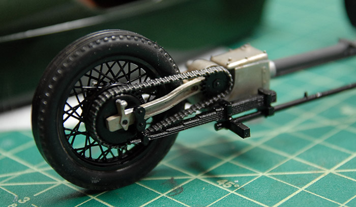
Below you can see a painted wheel, tire mounted, attached to the rear drive assembly. This whole assembly ends up being covered by the body, though, so there were some things here that I would usually fix, but decided not to bother with in this case. As a side note, to anyone else who may attempt this kit: The instructions mention dipping the tires in warm water in order to soften them before stretching them around the wheels. Use HOT water. It took me a few tries, with increasing warm/hot water to get the tires onto the wheels, and I managed to damage a few spokes. Using very hot water from the start would probably avoid any damage.
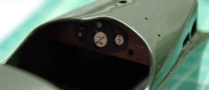
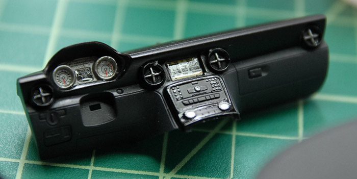
Below you can see the fairly simple dash board, with decals applied. The kit came with some very thick lenses for these gauges, but I decided to just use some clear parts cement to coat them instead, so that the graphics could still be seen.
Below you can see the frame all together, and the body painted with the interior painted and attached.
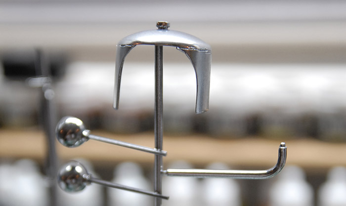
Here I'll touch upon something that will be addressed more in the next blog post: conversion from an air-cooled engine to a water-cooled one. The first part of that involved reshaping the front cowl a bit. The model part also had a very large raised band where there should have been a barely sunken weld bead. I reshaped the front opening a bit to give some curve to the sides and then cut off the raised ridge and used a heated sewing pin to carve a bit of a weld bead. Below you can see the reshaped cowl along with a few other parts after getting a coat of primer, black gloss and Alclad chrome paint.
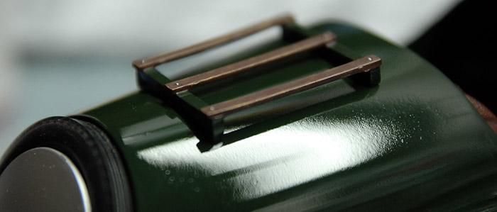
Finally, below you can see the rear rack mounted and a general indication of the quality of the paint job on this one. It's generally better than the SLS model, but still not quite what I was hoping for. This one is Tamiya british green and clear paints right from the can. I've decided that after this model is done, I'm just going to get a bunch of cheap car kits and just spend some time practicing my painting techniques on the bodies of those models.
Thanks for reading, and tune in for the next post, which will have some interesting new developments in model building!
Often, when I pick out kits to build, I do so because of the difficulty and complexity of the kit. I look for well-engineered kits, with lots of extras like photo-etch, metal parts, great decals, etc. This kit, on the other hand, I picked out because I really like the Morgan Three Wheeler. I've seen a few in person and always though that they were just really cool vehicles.
As a result of that method of kit selection, this one ended up taking quite a bit of extra work to make it acceptable. Below you can see the parts as they came out of the box: A few trees of a fairly soft grey plastic, some hard-ish rubber tires, some clear parts, a length of tubing for the engine and one tree of thickly-coated chrome parts.
First and foremost, I knew that the chrome parts were just not going to cut it. The varnish/primer that they use under the chrome was on there pretty thick, and in combination with the chrome paint, was filling in many of the details on the parts. That's not evening mentioning the fundamental problem with parts that are painted on the trees: The spots that are left unpainted on the parts once they are cut off the sprue. I decided to give a technique a try that I had read about online and in magazines: de-chroming the parts with Bleche-wite. Bleche-wite is a cleaner that is meant to whiten the whitewalls of tires. It's a pretty aggressive cleaner, so should be handled with care, in a well-ventilated area. I used a baking dish, with the bottle of cleaner emptied into it. I dropped the chrome sprue in there and covered it with plastic wrap. I found that it took a couple multi-hour sessions to get all the chrome off, but because this solvent isn't as aggressive as something like lacquer thinner, I didn't have to worry about the plastic itself dissolving. If you are going to try this yourself, I recommend giving it a few hours in the cleaner and then giving it a light scrubbing with a toothbrush (don't use the brush afterward, despite the tooth-whitening potential), and repeat that process until all the chrome and underlying varnish is all gone.
With that out of the way, I should probably mention something about this kit: It is a mess. Compared to many of the other kits that I have built, from the likes of Tamiya, Hobbyboss and Dragon, this one is of markedly lower quality. There is heaps of flash, the registration between the mold halves is not very good, there are ejector pin marks and sinks all over the place and it just requires a great deal of work to get into shape.
That said, I began by getting the body into a state that is ready for primer and paint. There were sinks on the exterior of the body in every place where there were structural braces on the inside. I ended up thinning some green Squadron putty with some lacquer thinner and spreading that over these areas. After that, I worked my way through various grits of sandpaper, wet sanding until it was smooth enough to be primed. Below you can see the exterior has been sanded, but the rear tire area still needs to be cleaned up.
Also, while consulting some reference, I determined that the way the instructions wanted me to put the wheel halves together would have resulted in wheels that didn't really look like the real things. The 1:1 car's wire wheels look to have an offset pattern, making for a much more visually-dense criss-cross pattern. The way the parts aligned resulted in all the spokes lining up, making for a much simpler look. I wanted the more complex look, so I shaved off the locator pins and offset the halves a few degrees. Below you can see the stock and offset locations of the wheel halves.
Some thing unusual about this kit is that it is constructed very much like the real car, with an underlying frame that the body sits on top of. While I'm not sure if this was the best idea, since the plastic that this kit is made of is pretty soft and not the best structural material, that is how it is made, so that is what I had to work with. While assembling the front end, I did notice that one of the bracing bars was cast out of scale, so I just replaced it with some extra brass rod that I had laying around, bent to match.
Below you can see a painted wheel, tire mounted, attached to the rear drive assembly. This whole assembly ends up being covered by the body, though, so there were some things here that I would usually fix, but decided not to bother with in this case. As a side note, to anyone else who may attempt this kit: The instructions mention dipping the tires in warm water in order to soften them before stretching them around the wheels. Use HOT water. It took me a few tries, with increasing warm/hot water to get the tires onto the wheels, and I managed to damage a few spokes. Using very hot water from the start would probably avoid any damage.
Below you can see the fairly simple dash board, with decals applied. The kit came with some very thick lenses for these gauges, but I decided to just use some clear parts cement to coat them instead, so that the graphics could still be seen.
Below you can see the frame all together, and the body painted with the interior painted and attached.
Here I'll touch upon something that will be addressed more in the next blog post: conversion from an air-cooled engine to a water-cooled one. The first part of that involved reshaping the front cowl a bit. The model part also had a very large raised band where there should have been a barely sunken weld bead. I reshaped the front opening a bit to give some curve to the sides and then cut off the raised ridge and used a heated sewing pin to carve a bit of a weld bead. Below you can see the reshaped cowl along with a few other parts after getting a coat of primer, black gloss and Alclad chrome paint.
Finally, below you can see the rear rack mounted and a general indication of the quality of the paint job on this one. It's generally better than the SLS model, but still not quite what I was hoping for. This one is Tamiya british green and clear paints right from the can. I've decided that after this model is done, I'm just going to get a bunch of cheap car kits and just spend some time practicing my painting techniques on the bodies of those models.
Thanks for reading, and tune in for the next post, which will have some interesting new developments in model building!
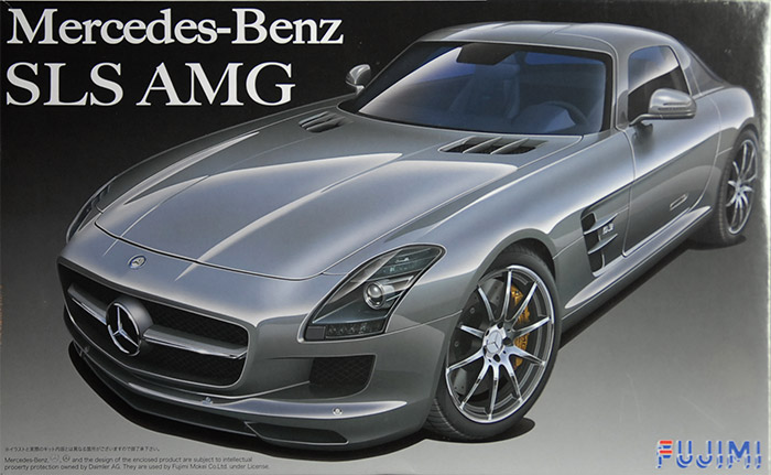
Mercedes-Benz SLS AMG
01 - December - 2013 - 12:14
In an effort to get better at shiny car paint finishes, I've decided to do a number of cars in a row. The first in this line of increasingly-shiny vehicles is this Mercedes-Benz SLS AMG.
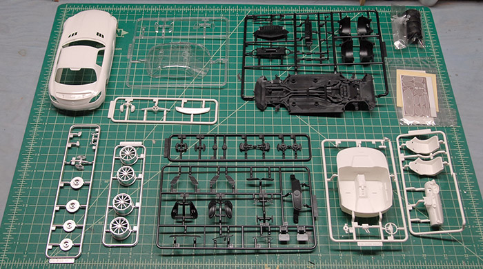
Below, you can see the various trees of parts. The body is a single piece, with no opening panels. There are a few parts (wheels, brakes, ducts) that are pre-painted in a satin metal that looks decent. There is also a bit of photo-etch that provide for replacing some of the plastic grills.
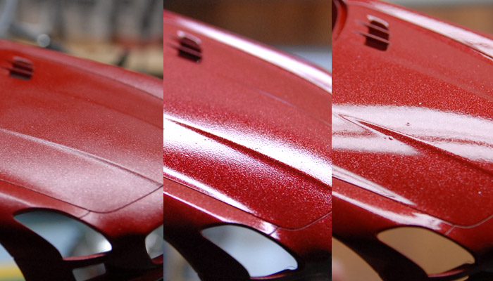
Since the goal of this project is practicing my car paint finishing, let's just right to that. I had been doing some reading on various scale modeling forums (Fine Scale Modeler forums, mostly) and had read good things about Testors one-coat lacquer, so I decided to give that a try. I bought one of their metallic red colors and some of their clear coat. After sanding out some seams and priming, the body and spoiler were ready for paint. In the image below, you can see how it looks after a few coats of the red paint (first image), after one coat of the clear coat (middle) and after two coats of the clear coat (third image). As you can see, I had a good deal of trouble trying to get the paint to go on glossy, always ending up with a pebbly finish. When the clear went over that, it smoothed it out a bit, but was still not the best.
In an effort to get a better finish, I took a series of sanding pads to the surface, smoothing out the orange peel texture and trying to get a better surface to spray more clear coat on to. Below you can see a few stages in the sanding process.
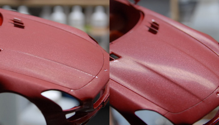
The problem I was having with this metallic paint was that as I sanded it, the metal flakes would come to the surface, and be silver spots, instead of the red-tinted flakes that they were when deeper in the paint. I suppose that is the nature of metal flake paint, but it definitely made things a bit more difficult as far as getting a nice consistent look.
After some more clear coat, the paint finish was definitely better, as you can see in the final images, but still not as good as I would like, as it still had a little bit of orange peel.
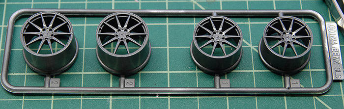
In reference that I found, the wheels also were available in a gunmetal color, which I think goes much better with the metallic red paint. Below you can see the wheels after being sprayed with some Alclad gunmetal paint and a couple coats of clear gloss.
The brake calipers, after some paint, decals, and clear.
The chassis, after being painted black, masked for spraying of the various metal bits (exhaust, braces, engine, etc).
After the painting:
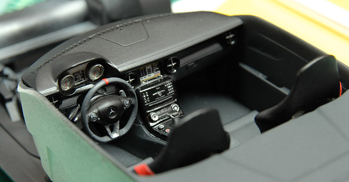
The interior of the real car looks to have a two-tone black/grey scheme (it may be black leather and Alcantara). I made an effort to replicate that scheme with black and grey paint and some selective application of some gloss varnish (from Vallejo). The dash after painting, and decals:
Since the kit didn't come with any seat belts, I used a bit of masking tape to make some, and added some buckles that I already had.
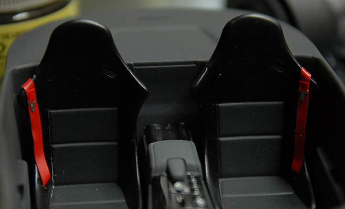
Below you can see the completed interior, before the top and bottom of the car was put together.
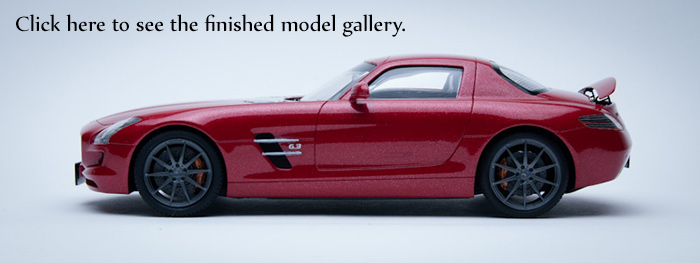
And finally, everything was put together and a bit of Tamiya model wax applied to clean and shine things up. Click on the image below to see the gallery of photos of the finished model:
Below, you can see the various trees of parts. The body is a single piece, with no opening panels. There are a few parts (wheels, brakes, ducts) that are pre-painted in a satin metal that looks decent. There is also a bit of photo-etch that provide for replacing some of the plastic grills.
Since the goal of this project is practicing my car paint finishing, let's just right to that. I had been doing some reading on various scale modeling forums (Fine Scale Modeler forums, mostly) and had read good things about Testors one-coat lacquer, so I decided to give that a try. I bought one of their metallic red colors and some of their clear coat. After sanding out some seams and priming, the body and spoiler were ready for paint. In the image below, you can see how it looks after a few coats of the red paint (first image), after one coat of the clear coat (middle) and after two coats of the clear coat (third image). As you can see, I had a good deal of trouble trying to get the paint to go on glossy, always ending up with a pebbly finish. When the clear went over that, it smoothed it out a bit, but was still not the best.
In an effort to get a better finish, I took a series of sanding pads to the surface, smoothing out the orange peel texture and trying to get a better surface to spray more clear coat on to. Below you can see a few stages in the sanding process.
The problem I was having with this metallic paint was that as I sanded it, the metal flakes would come to the surface, and be silver spots, instead of the red-tinted flakes that they were when deeper in the paint. I suppose that is the nature of metal flake paint, but it definitely made things a bit more difficult as far as getting a nice consistent look.
After some more clear coat, the paint finish was definitely better, as you can see in the final images, but still not as good as I would like, as it still had a little bit of orange peel.
In reference that I found, the wheels also were available in a gunmetal color, which I think goes much better with the metallic red paint. Below you can see the wheels after being sprayed with some Alclad gunmetal paint and a couple coats of clear gloss.
The brake calipers, after some paint, decals, and clear.
The chassis, after being painted black, masked for spraying of the various metal bits (exhaust, braces, engine, etc).
After the painting:
The interior of the real car looks to have a two-tone black/grey scheme (it may be black leather and Alcantara). I made an effort to replicate that scheme with black and grey paint and some selective application of some gloss varnish (from Vallejo). The dash after painting, and decals:
Since the kit didn't come with any seat belts, I used a bit of masking tape to make some, and added some buckles that I already had.
Below you can see the completed interior, before the top and bottom of the car was put together.
And finally, everything was put together and a bit of Tamiya model wax applied to clean and shine things up. Click on the image below to see the gallery of photos of the finished model:
F-84e Thunderjet Completion
10 - June - 2013 - 20:42
Picking up where the last post left off, the decal work continued. It was pretty straight-forward, with liberal use of MicroSet and MicroSol to try to get the decals to sink into the panel lines and rivets. This was generally successful, but if you look closely in the finished model galley, you can see a few areas where the decals were a bit stubborn. This was mostly on the large wing insignias and the stars and bars on the sides of the fuselage. I'm just guessing that the white layer was a little tougher than the others, making those decals a bit harder to soften.
With all the decals on, I sprayed the whole jet with a few coats of Testors Flat Clear to kill the gloss and give everything the same sheen. Below you can see the canopy with the masking removed and everything with a nice dull finish.
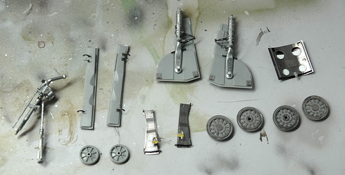
The last step in construction was to assemble all the fiddly bits that are prone to breakage, and thus left to the end. This was also an area that had the most replacement with either kit metal parts or Eduard photo etch detail parts. The landing gear all had metal parts that came with the kit as well as a few small details that were from the Eduard kit. The air brake and small gear doors (upper left and lower center, respectively) were full replacements with Eduard parts, although with the air brake, I completely misplaced some vent louvres, so I had to make a few replacements with very thin plastic card (the white you can see through the holes in the image below). Below you can see them all built and ready for priming and painting.
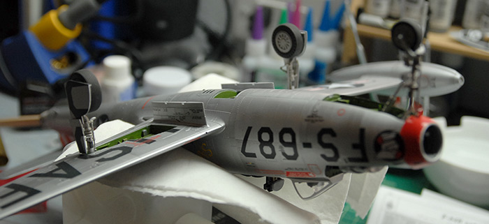
Those parts all got the same paint treatment as the body, and were then decalled, sprayed with flat, and then assembled. Below, you can see the jet propped at a funny angle as the epoxy on the landing gear sets.
This is where I got a bit lazy with the documentation photography. But after this point, all that was left was some weathering, and the assembly and painting of the two bombs that attach to the pylons. Weathering was done using a neutral wash from MIG. I tested out using black watercolors first, but it just didn't like the flat clear coat, and just wanted to bead up and make black water spots. I settled on a fairly easy technique where I'd paint on the neutral wash with a small paint brush, covering all the panel lines and rivet lines. Then, I'd let it dry for at least a few hours (so that it was completely dry), and then go back over it with a lint-free wipe, dampened with thinner (the sort that is meant to work with MIG pigments). That wiped most of the wash away, but left just enough behind in the lines and rivets to be pleasing. It also left just a bit on the surface to make things look not quite so clean.
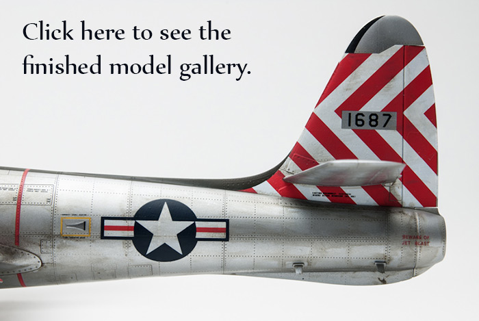
Well, that one is all wrapped up, so check out the images of the finished model by clicking on the image below. Thanks for reading!
With all the decals on, I sprayed the whole jet with a few coats of Testors Flat Clear to kill the gloss and give everything the same sheen. Below you can see the canopy with the masking removed and everything with a nice dull finish.
The last step in construction was to assemble all the fiddly bits that are prone to breakage, and thus left to the end. This was also an area that had the most replacement with either kit metal parts or Eduard photo etch detail parts. The landing gear all had metal parts that came with the kit as well as a few small details that were from the Eduard kit. The air brake and small gear doors (upper left and lower center, respectively) were full replacements with Eduard parts, although with the air brake, I completely misplaced some vent louvres, so I had to make a few replacements with very thin plastic card (the white you can see through the holes in the image below). Below you can see them all built and ready for priming and painting.
Those parts all got the same paint treatment as the body, and were then decalled, sprayed with flat, and then assembled. Below, you can see the jet propped at a funny angle as the epoxy on the landing gear sets.
This is where I got a bit lazy with the documentation photography. But after this point, all that was left was some weathering, and the assembly and painting of the two bombs that attach to the pylons. Weathering was done using a neutral wash from MIG. I tested out using black watercolors first, but it just didn't like the flat clear coat, and just wanted to bead up and make black water spots. I settled on a fairly easy technique where I'd paint on the neutral wash with a small paint brush, covering all the panel lines and rivet lines. Then, I'd let it dry for at least a few hours (so that it was completely dry), and then go back over it with a lint-free wipe, dampened with thinner (the sort that is meant to work with MIG pigments). That wiped most of the wash away, but left just enough behind in the lines and rivets to be pleasing. It also left just a bit on the surface to make things look not quite so clean.
Well, that one is all wrapped up, so check out the images of the finished model by clicking on the image below. Thanks for reading!
F-84e Progress
27 - April - 2013 - 20:25
Hey there! It's been ages, I know, but I'm back with an update on my progress on the F-84e. Since the last update, lots of other exciting non-model-related things have happened, such as me finishing work on Monsters University (in theaters June 21st!), some vacation, and misc other tasks. But recently, I decided to quit slacking around and try to make some real progress on this model. Here's what I have been up to…
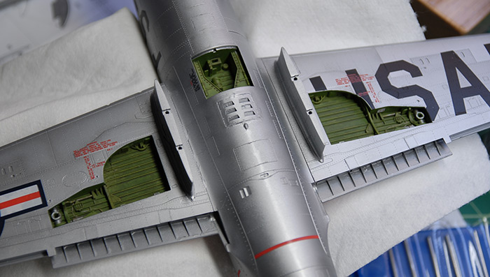
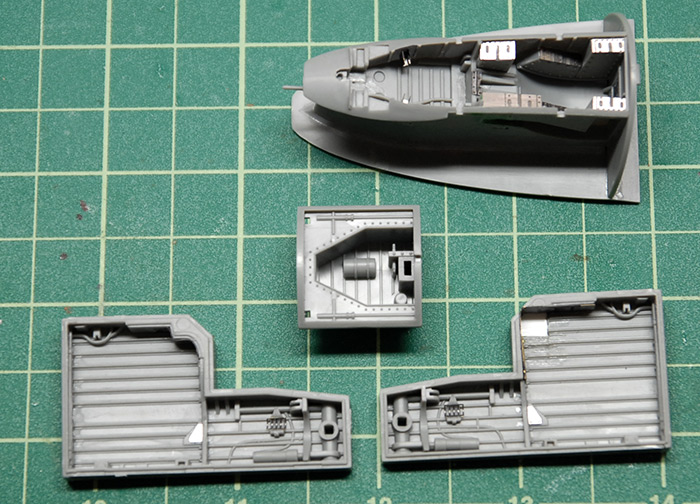
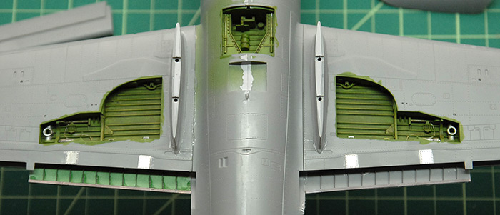
After the cockpit, the next step was the landing gear and air brake bays. The detail kit from Eduard included various panels and brackets for these, so you can see a few of those in the images below. The Eduard instructions also called for me to cut one of the corners out of one rear gear bay and replace it with an etch panel (lower right, in the below photo). This was questionably successful, as the part that I was supposed to replace the floor corner with didn't fit very well and the thickness between the plastic floor parts and the etch version just weren't close enough to blend together. I decided to just let it slide and replaced the etch floor with some polystyrene card and leave it at that.
Below you can see the same bays after priming and painting in a base green. They had various details picked out by hand in steel paint, the raised bits picked out with a lighter shade via dry brushing and the whole things hit with a grungy brown wash to give it all a bit of dirt.
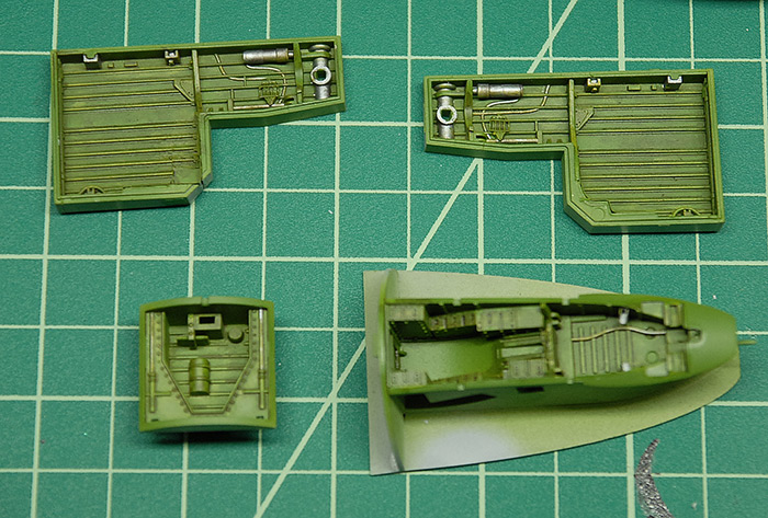
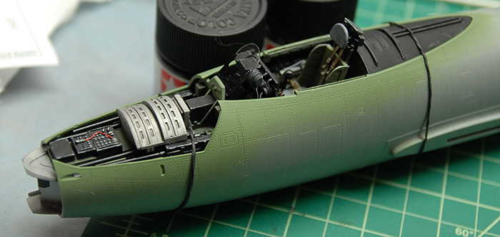
Next up was prepping the fuselage halves for assembly. Since the front gear bay, air brake bay and cockpit are all locked between the halved when they go together, the inside of the fuselage halves need to be painted to match where appropriate. As you can see in the image below, most of it was painted the same green as the cockpit. The metallic bit at the front is the area that is seen through the nose intake, which, according to reference photos, matches the exterior aluminum color.
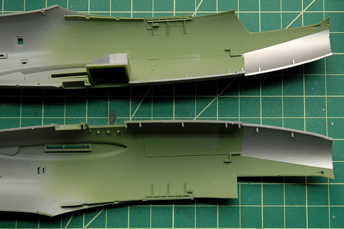
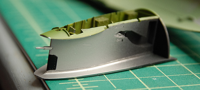
Similarly, the front landing gear bay had to have the upper section of it painted that same aluminum, since it goes in that same intake, and splits the flow of air. I'm not sure what the little black panel is, but all the reference I could find showed it being black and shiny, so there you have it.
Below you can see the fuselage halves in place, while the glue is drying, with the cockpit sandwiched in between.
Skipping ahead a bit, the next step was to assemble the wings, which sandwich the rear gear bays in them. This was another area where the Eduard detail kit had a few extras for me to add. The place where the flaps go had an extra photo-etch piece, which showed a bit of the structure of the wing itself. These were a little tricky, as it required that a little bit of the wing be cut away to make room for the flap connections (which were also replaced by etch parts). You can see in the photo below that the two sides are different colors, as I first tried filling in the gaps with super glue, on the right side, and then, not being happy with that (but also not willing to take it back apart) I took a different approach on the left side and filled the area in with green putty. The putty was then sanded back into a flat surface which fit the etch part a little better. While neither side is perfect, I'm hoping that the imperfections are mostly covered by the flaps, once they are in place.
Also visible below is a bit of the filling that was added between the fuselage halves to help cover up the seam.
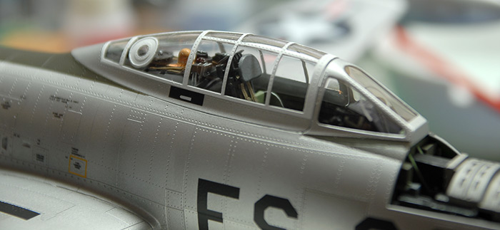
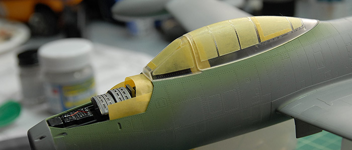
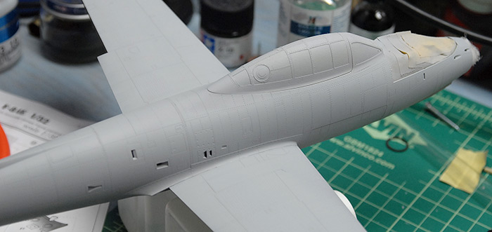
Next up was to mask the canopy parts, using the precut masks that came with the Eduard kit. Generally, they fit well, but were tricky to place in a few cases. You can see below where I ended up just adding a little bit of extra tape, because it was giving me too much trouble getting the mask into just the right place. Also, this is where I ran into a bit of a snag. I discovered that, with all the cockpit stuff in place, the front canopy section wouldn't actually fit over it.
Whoops!
The HUD glass was sticking up a bit too far to allow the canopy to fit into its spot. What I ended up doing was detaching a few of the parts that held the HUD and then shortened a few of them, so that, once back in place, they were low enough to allow the canopy to fit. A side note here: I found that the clear HUD piece that came with the kit seemed strangely large. If I were to go back and do it again, I'd probably make a new piece that was quite a bit smaller and substitute that instead. But, by the time I got far enough along and realized that its scale didn't really match the reference photos I had, I really wasn't up for tearing it apart again and building something new. Oh well :)
The rear canopy section is taped in place on the front and held in the back with a tiny dab of clear-parts glue, with the thought that it'll be easy to pop back off after painting.
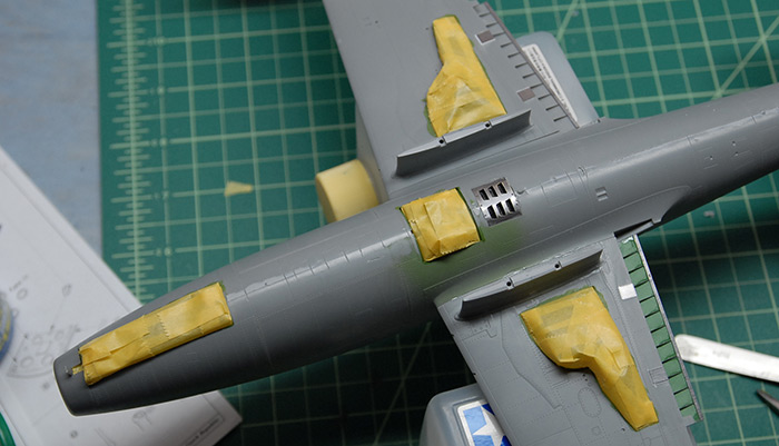
Below you can see the various gear bays masked off and ready for priming and painting.
The various flaps and such with the standard scrap-sprue handles, also ready for priming and painting.
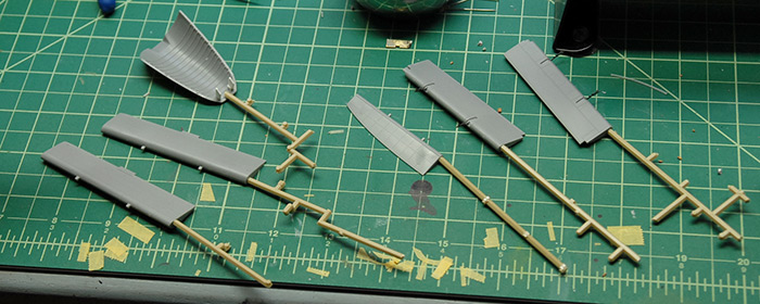
The model after priming with Mr Surfacer 1200:
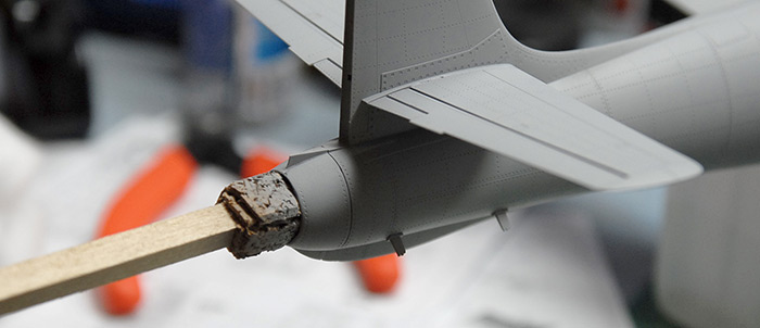
I made myself a little handle out of some scrap bass wood I had around and some self-adhesive cork sheeting I had left over from when I lined my desk drawers. I'm pretty sure I may have snapped off a few of the etch parts inside the exhaust, but I'll fix those later ;)
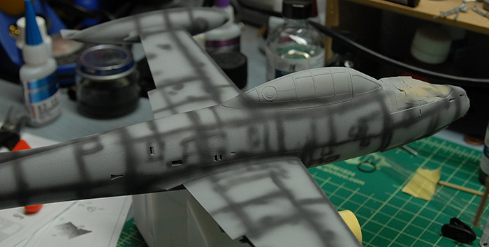
Next up was some pre-shading on the panel lines with some Tamiya German Grey. The idea here is to just give some contrasting tones that can subtly show through the metallic paint later on. This helps break up the otherwise flat surface and hints at wear and tear.
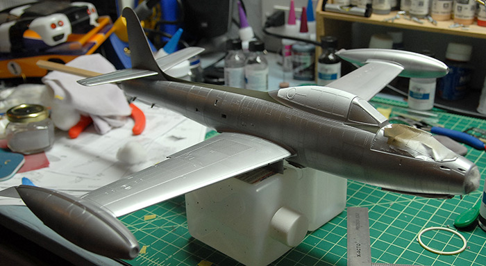
Next up was a base coat of Alcald Aluminum paint. Then various panels were masked off and painted with a darker aluminum shade. Then more panels were masked and painted with a lighter aluminum shade. Next, the top of the canopy was masked and painted flat white. Finally, the top of the fuselage was masked and painted olive drab.
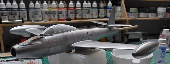
In the below photo, it is a little easier to see some of the variation in the panel shades. These will be picked out a bit more later on with weathering and pin washing.
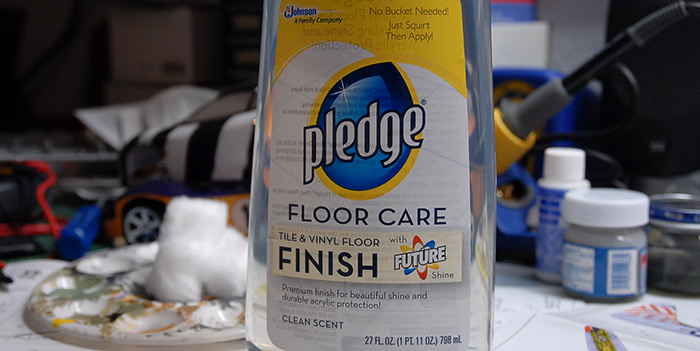
Next up were two coats of Pledge Future, to prep for decals. For those not familiar with this stuff, it is a floor care product that is widely used by modelers since it has a number of features that make it great to work with. First off, it can be airbrushed directly, without any diluting (very handy). It provides a nice glossy surface, to help prevent silvering (this is the reason to want a gloss coat at this point) with the decals and also lays nice and flat after drying, so you don't have to worry about it adding a ton of thickness or filling in fine panel seams. Also, it is an acrylic product, so I can put it right over the fragile Alclad paint and not have to worry about the solvents eating away the paint. It also smells nice :)
Since it's no longer called 'Future', I figured I'd add an image of what my bottle looks like, so that others wanting to use the same had an easier time tracking it down (it can be ordered from amazon.com).
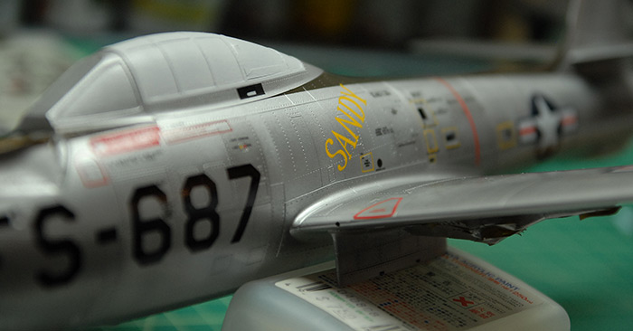
And finally, here's a little teaser of the in-progress decal work. At this time, I've got one side pretty much complete decal-wise and am moving on to the other side.
Once the decals are all on, then it's back to the landing gear, in order to give this bird some legs to stand on. Then comes an overcoating of flat clear to kill the gloss from the Future, removal of the canopy masks and then final assembly. I'm still debating how I want to display this one, so I'll leave thoughts on that to a later post.
Thanks for reading!
After the cockpit, the next step was the landing gear and air brake bays. The detail kit from Eduard included various panels and brackets for these, so you can see a few of those in the images below. The Eduard instructions also called for me to cut one of the corners out of one rear gear bay and replace it with an etch panel (lower right, in the below photo). This was questionably successful, as the part that I was supposed to replace the floor corner with didn't fit very well and the thickness between the plastic floor parts and the etch version just weren't close enough to blend together. I decided to just let it slide and replaced the etch floor with some polystyrene card and leave it at that.
Below you can see the same bays after priming and painting in a base green. They had various details picked out by hand in steel paint, the raised bits picked out with a lighter shade via dry brushing and the whole things hit with a grungy brown wash to give it all a bit of dirt.
Next up was prepping the fuselage halves for assembly. Since the front gear bay, air brake bay and cockpit are all locked between the halved when they go together, the inside of the fuselage halves need to be painted to match where appropriate. As you can see in the image below, most of it was painted the same green as the cockpit. The metallic bit at the front is the area that is seen through the nose intake, which, according to reference photos, matches the exterior aluminum color.
Similarly, the front landing gear bay had to have the upper section of it painted that same aluminum, since it goes in that same intake, and splits the flow of air. I'm not sure what the little black panel is, but all the reference I could find showed it being black and shiny, so there you have it.
Below you can see the fuselage halves in place, while the glue is drying, with the cockpit sandwiched in between.
Skipping ahead a bit, the next step was to assemble the wings, which sandwich the rear gear bays in them. This was another area where the Eduard detail kit had a few extras for me to add. The place where the flaps go had an extra photo-etch piece, which showed a bit of the structure of the wing itself. These were a little tricky, as it required that a little bit of the wing be cut away to make room for the flap connections (which were also replaced by etch parts). You can see in the photo below that the two sides are different colors, as I first tried filling in the gaps with super glue, on the right side, and then, not being happy with that (but also not willing to take it back apart) I took a different approach on the left side and filled the area in with green putty. The putty was then sanded back into a flat surface which fit the etch part a little better. While neither side is perfect, I'm hoping that the imperfections are mostly covered by the flaps, once they are in place.
Also visible below is a bit of the filling that was added between the fuselage halves to help cover up the seam.
Next up was to mask the canopy parts, using the precut masks that came with the Eduard kit. Generally, they fit well, but were tricky to place in a few cases. You can see below where I ended up just adding a little bit of extra tape, because it was giving me too much trouble getting the mask into just the right place. Also, this is where I ran into a bit of a snag. I discovered that, with all the cockpit stuff in place, the front canopy section wouldn't actually fit over it.
Whoops!
The HUD glass was sticking up a bit too far to allow the canopy to fit into its spot. What I ended up doing was detaching a few of the parts that held the HUD and then shortened a few of them, so that, once back in place, they were low enough to allow the canopy to fit. A side note here: I found that the clear HUD piece that came with the kit seemed strangely large. If I were to go back and do it again, I'd probably make a new piece that was quite a bit smaller and substitute that instead. But, by the time I got far enough along and realized that its scale didn't really match the reference photos I had, I really wasn't up for tearing it apart again and building something new. Oh well :)
The rear canopy section is taped in place on the front and held in the back with a tiny dab of clear-parts glue, with the thought that it'll be easy to pop back off after painting.
Below you can see the various gear bays masked off and ready for priming and painting.
The various flaps and such with the standard scrap-sprue handles, also ready for priming and painting.
The model after priming with Mr Surfacer 1200:
I made myself a little handle out of some scrap bass wood I had around and some self-adhesive cork sheeting I had left over from when I lined my desk drawers. I'm pretty sure I may have snapped off a few of the etch parts inside the exhaust, but I'll fix those later ;)
Next up was some pre-shading on the panel lines with some Tamiya German Grey. The idea here is to just give some contrasting tones that can subtly show through the metallic paint later on. This helps break up the otherwise flat surface and hints at wear and tear.
Next up was a base coat of Alcald Aluminum paint. Then various panels were masked off and painted with a darker aluminum shade. Then more panels were masked and painted with a lighter aluminum shade. Next, the top of the canopy was masked and painted flat white. Finally, the top of the fuselage was masked and painted olive drab.
In the below photo, it is a little easier to see some of the variation in the panel shades. These will be picked out a bit more later on with weathering and pin washing.
Next up were two coats of Pledge Future, to prep for decals. For those not familiar with this stuff, it is a floor care product that is widely used by modelers since it has a number of features that make it great to work with. First off, it can be airbrushed directly, without any diluting (very handy). It provides a nice glossy surface, to help prevent silvering (this is the reason to want a gloss coat at this point) with the decals and also lays nice and flat after drying, so you don't have to worry about it adding a ton of thickness or filling in fine panel seams. Also, it is an acrylic product, so I can put it right over the fragile Alclad paint and not have to worry about the solvents eating away the paint. It also smells nice :)
Since it's no longer called 'Future', I figured I'd add an image of what my bottle looks like, so that others wanting to use the same had an easier time tracking it down (it can be ordered from amazon.com).
And finally, here's a little teaser of the in-progress decal work. At this time, I've got one side pretty much complete decal-wise and am moving on to the other side.
Once the decals are all on, then it's back to the landing gear, in order to give this bird some legs to stand on. Then comes an overcoating of flat clear to kill the gloss from the Future, removal of the canopy masks and then final assembly. I'm still debating how I want to display this one, so I'll leave thoughts on that to a later post.
Thanks for reading!
New project: F-84e Thunderjet
13 - January - 2013 - 18:28
With the Hornethopter wrapped up, it was time to move along to the next project. I bought this kit a year or so ago for a few different reasons. First, the kit looked well made and came with a number of things that you usually have to pay extra for and order separately, such as metal landing gear. It also was 1:32 scale, which is on the larger side for aircraft, allowing for more detail and a little room to work. I had bought this with the intention of learning more about natural metal finishing, since that wasn't something I had done much of previously. Finally, I haven't made a plastic aircraft model since I was maybe 13 years old, so it seemed like it would be a fun change of pace.
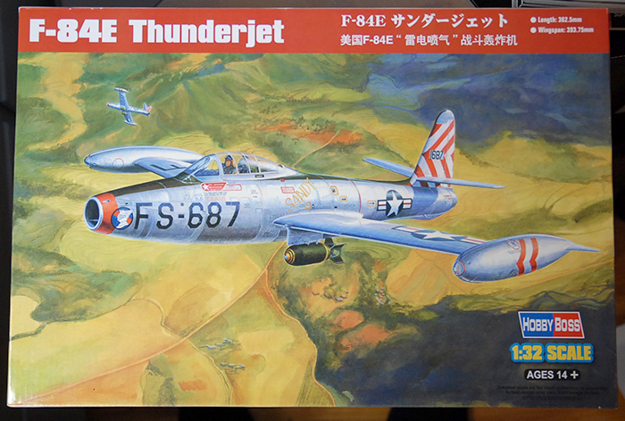
This one is made by HobbyBoss and is of the Korean-war-era F-84E Thunderjet.
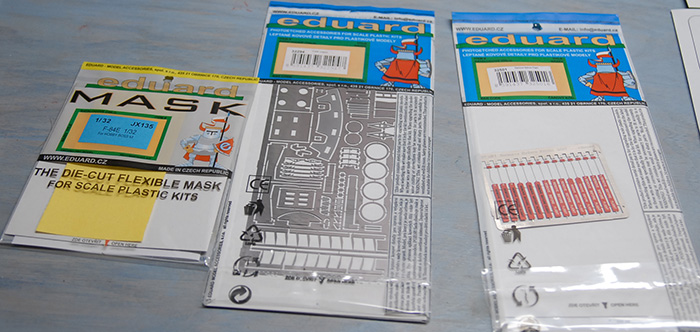
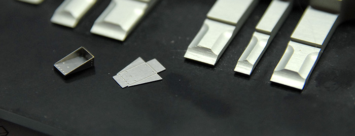
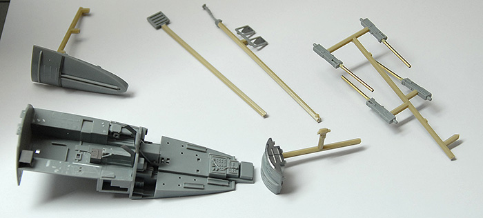
Since I don't seem to be able to leave well enough alone, I also ordered the 'Big Ed' kit of detailing parts from Eduard. It consists of four sets of photo-etched metal (seat belts, cockpit details, exterior details, and remove-before-flight tags) and one set of pre-cut canopy masks. Below you can see, from left to right, the canopy masks, exterior detail kit and remove-before-flight tags.
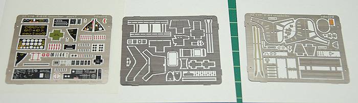
Below you can see the two frets of photo-etch for the cockpit details (left two) and one (partially used at this point) fret for the seat belt and ejector seat upgrades.
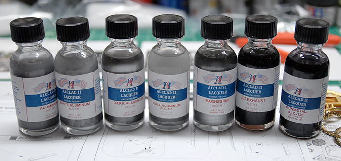
While I was ordering things, I expanded my collection of Alclad metallic paints by ordering a few more. These were chosen to provide a few similar shades of aluminum for the main aircraft skin as well as a few other colors that I thought would be handy (gunmetal, jet exhaust)
With the addition of all of the upgrade parts, I found that I needed to be much more careful of the order in which things are assembled. In addition, there was quite a bit of work that had to be done to the plastic parts, in order to shave off raised details that were to be replaced by photo-etched parts. To start, though, I put together the seat belts, since they were not replacing any kit part, making them safe to build without worry. The parts are pre-printed photo-etched metal, which is pretty cool, but also a little shinier than I would prefer and a bit tricky to bend without the paint flaking off. Here are the belts after being assembled but before bending them into final shape on the seat.
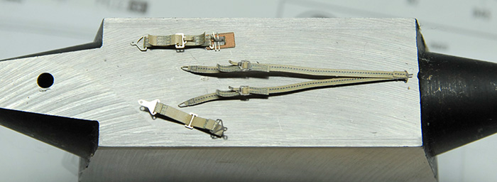
Here is a close-up of the little foot-rest-looking things for the seat in bent and unbent form. They are on a Hold-and-Fold bender (very handy!).
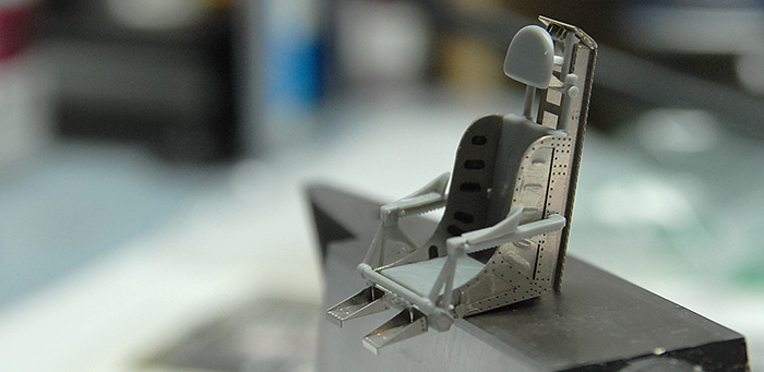
Here is the seat, pretty much all assembled with kit and upgrade parts mixing. Although, as I discovered later on, the upgrade parts seem to actually be for the F-84G seat rather than the F-84E (at least so I have read, as I wouldn't know for sure myself, and have had a hard time finding good reference). What this meant, though, was that the seat, with the new frame behind it, sat quite a bit further forward in the cockpit that the kit seat. This required a little bit of trimming and planning in order to get everything to fit again. Mostly just taking a bit out of the center pillar and moving the control stick forward. Also, I made a few modifications to the kit part that helps align the seat in the cockpit, so that it would fit in there securely.
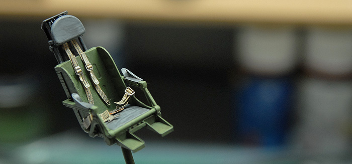
Here is the seat with paint. I also had a hard time finding good reference of this cockpit as far as color goes. Most of the reference is of the F-84G, and most of THAT is of planes that have long since been decommissioned, been repainted, and have been sitting in museums for a while. Even checking other models that have been built, the colored ranged from all black, to all green to a mixture of both. Since my seat was already a bit mismatched version-wise, I decided to just go with a mixture of black and interior green. If I was a stickler for historical detail, I'd probably rebuild the seat to remove the back structure. But I'm not a stickler like that, and I like the way it looks, so I suppose this one will never win any IPMS awards ;)
Next up was to start putting together the cockpit tub. This is where is started to get a bit trickier, as there were many kit parts that were being replaced by the upgrade parts and many kit parts that just needed altering. The kit parts had many of the controls molded into the plastic, but since those were being replaced by more pre-printed etched parts, I had to shave off much of the raised details. There were also a few boxes and cylinders that either needed to be cut off and replaced with folded etch or needed to be cut off and saved to be put back on top of the printed etch parts later.
Directly connected to the front of the cockpit tub is the gun bay, with four machine cannons. Looking at the kit parts, the gun barrels were not looking so good. They were a little soft around the edges, didn't have a hole in the end, and had a mold seam that I would have to clean up. I had seen various articles in Fine Scale Modeler magazine where people used fancy turned brass gun barrels that looked just fabulous. Not having anything like that, I instead dug into a bag of scrap metal bits that I got at the local Ace Hardware, and found some lengths of 1/16" brass tubing that I could cut down and use instead. With a bit of careful cutting (I put the tube on the desk, put a sharp x-acto on top and slowly rolled back and forth, letting the knife cut through the soft metal with only light pressure), I ended up with four 1" long gun barrels that looked much better than the kit versions.
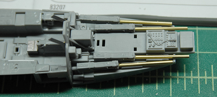
Below you can see the various cockpit and gun bay parts attached to scrap plastic and ready for painting.
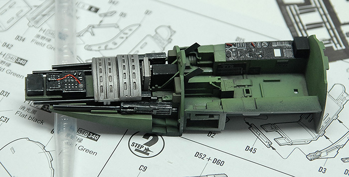
Below is the current state of the cockpit and gun bay. The gun bay parts are not glued yet, but just put in there to demonstrate how they go together. Also, only a few bits of the pre-printed etch have gone into the cockpit so far, and they will get touched up a bit later and possibly sprayed with a matte medium overcoat in order to dull them down a bit (pending a paint interaction test, to avoid any possible mishaps).
The painting was made up of a base coat of Mr Surfacer 1200, then a layer of Tamiya Dark Green (XF-61) followed by an overcoat of Tamiya Cockpit Green (XF-71), all sprayed with my Paasche Talon airbrush. On the lighter green, I avoided the corners a bit, to let them stay a bit darker. The gun bay parts are Alclad Gunmetal and Dull Aluminum. Everything got a light wash of Abteilung Dark Mud in order to pick out some details and make it all a bit less clean. It still needs some selective dry-brushing of highlights, and much more of the photo-etched details, but that's for next time!
Thanks for reading!
This one is made by HobbyBoss and is of the Korean-war-era F-84E Thunderjet.
Since I don't seem to be able to leave well enough alone, I also ordered the 'Big Ed' kit of detailing parts from Eduard. It consists of four sets of photo-etched metal (seat belts, cockpit details, exterior details, and remove-before-flight tags) and one set of pre-cut canopy masks. Below you can see, from left to right, the canopy masks, exterior detail kit and remove-before-flight tags.
Below you can see the two frets of photo-etch for the cockpit details (left two) and one (partially used at this point) fret for the seat belt and ejector seat upgrades.
While I was ordering things, I expanded my collection of Alclad metallic paints by ordering a few more. These were chosen to provide a few similar shades of aluminum for the main aircraft skin as well as a few other colors that I thought would be handy (gunmetal, jet exhaust)
With the addition of all of the upgrade parts, I found that I needed to be much more careful of the order in which things are assembled. In addition, there was quite a bit of work that had to be done to the plastic parts, in order to shave off raised details that were to be replaced by photo-etched parts. To start, though, I put together the seat belts, since they were not replacing any kit part, making them safe to build without worry. The parts are pre-printed photo-etched metal, which is pretty cool, but also a little shinier than I would prefer and a bit tricky to bend without the paint flaking off. Here are the belts after being assembled but before bending them into final shape on the seat.
Here is a close-up of the little foot-rest-looking things for the seat in bent and unbent form. They are on a Hold-and-Fold bender (very handy!).
Here is the seat, pretty much all assembled with kit and upgrade parts mixing. Although, as I discovered later on, the upgrade parts seem to actually be for the F-84G seat rather than the F-84E (at least so I have read, as I wouldn't know for sure myself, and have had a hard time finding good reference). What this meant, though, was that the seat, with the new frame behind it, sat quite a bit further forward in the cockpit that the kit seat. This required a little bit of trimming and planning in order to get everything to fit again. Mostly just taking a bit out of the center pillar and moving the control stick forward. Also, I made a few modifications to the kit part that helps align the seat in the cockpit, so that it would fit in there securely.
Here is the seat with paint. I also had a hard time finding good reference of this cockpit as far as color goes. Most of the reference is of the F-84G, and most of THAT is of planes that have long since been decommissioned, been repainted, and have been sitting in museums for a while. Even checking other models that have been built, the colored ranged from all black, to all green to a mixture of both. Since my seat was already a bit mismatched version-wise, I decided to just go with a mixture of black and interior green. If I was a stickler for historical detail, I'd probably rebuild the seat to remove the back structure. But I'm not a stickler like that, and I like the way it looks, so I suppose this one will never win any IPMS awards ;)
Next up was to start putting together the cockpit tub. This is where is started to get a bit trickier, as there were many kit parts that were being replaced by the upgrade parts and many kit parts that just needed altering. The kit parts had many of the controls molded into the plastic, but since those were being replaced by more pre-printed etched parts, I had to shave off much of the raised details. There were also a few boxes and cylinders that either needed to be cut off and replaced with folded etch or needed to be cut off and saved to be put back on top of the printed etch parts later.
Directly connected to the front of the cockpit tub is the gun bay, with four machine cannons. Looking at the kit parts, the gun barrels were not looking so good. They were a little soft around the edges, didn't have a hole in the end, and had a mold seam that I would have to clean up. I had seen various articles in Fine Scale Modeler magazine where people used fancy turned brass gun barrels that looked just fabulous. Not having anything like that, I instead dug into a bag of scrap metal bits that I got at the local Ace Hardware, and found some lengths of 1/16" brass tubing that I could cut down and use instead. With a bit of careful cutting (I put the tube on the desk, put a sharp x-acto on top and slowly rolled back and forth, letting the knife cut through the soft metal with only light pressure), I ended up with four 1" long gun barrels that looked much better than the kit versions.
Below you can see the various cockpit and gun bay parts attached to scrap plastic and ready for painting.
Below is the current state of the cockpit and gun bay. The gun bay parts are not glued yet, but just put in there to demonstrate how they go together. Also, only a few bits of the pre-printed etch have gone into the cockpit so far, and they will get touched up a bit later and possibly sprayed with a matte medium overcoat in order to dull them down a bit (pending a paint interaction test, to avoid any possible mishaps).
The painting was made up of a base coat of Mr Surfacer 1200, then a layer of Tamiya Dark Green (XF-61) followed by an overcoat of Tamiya Cockpit Green (XF-71), all sprayed with my Paasche Talon airbrush. On the lighter green, I avoided the corners a bit, to let them stay a bit darker. The gun bay parts are Alclad Gunmetal and Dull Aluminum. Everything got a light wash of Abteilung Dark Mud in order to pick out some details and make it all a bit less clean. It still needs some selective dry-brushing of highlights, and much more of the photo-etched details, but that's for next time!
Thanks for reading!
Kröte - Finished and Photographed
04 - July - 2012 - 20:42
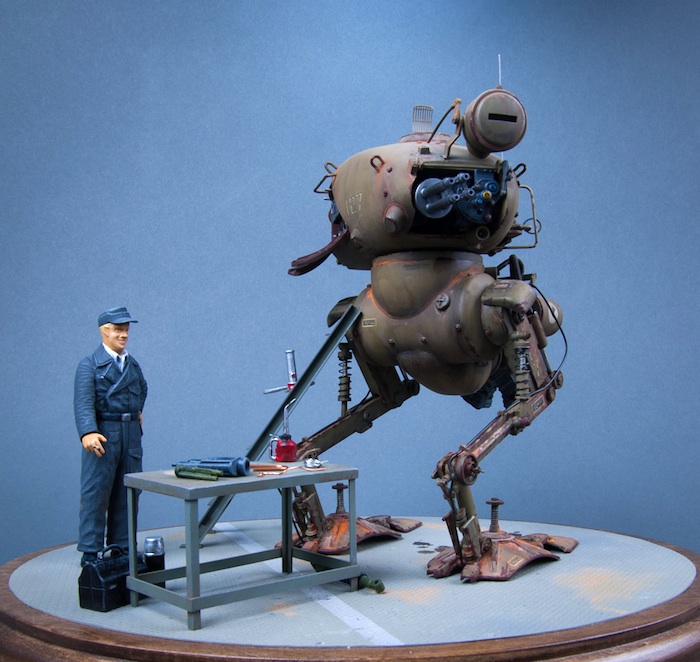
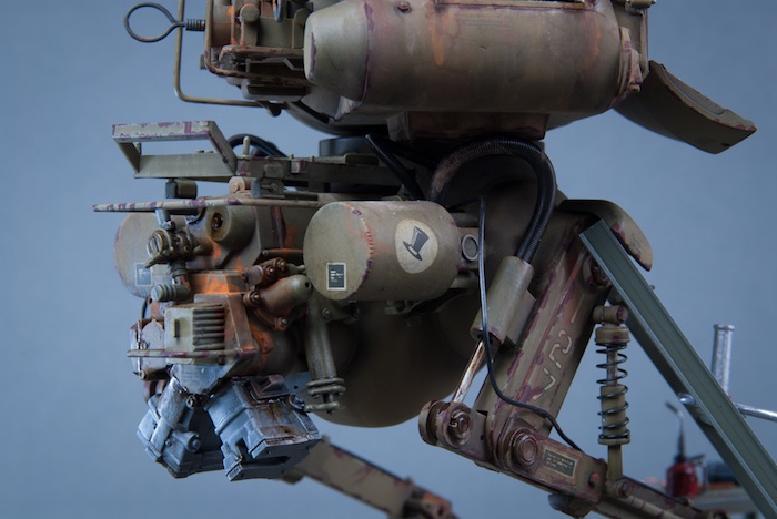
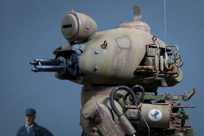
Another one wrapped up. Below you can see the finished product. Once I went to put everything together, I found that the concave bottom of the robot feet made it quite difficult to glue down to the base. I ended up having to build some additional structure on to the feet bottoms so that there was something of substance under there that could be glued down.
Weathering was done with MIG pigments and Abteilung oils. I also went back and added a good deal of red primer-colored paint along many of the edges to represent chipped and scraped paint. It's another new technique for me (since I don't do much armor modeling) and I feel that it was somewhat successful. Next time, though, I think I'll approach it a little differently, using some of the same salt-mask techniques on the flooring and maybe looking into a similar technique that uses hairspray as a masking agent.
Next, various washes of dark oils and pigments, spread around with mineral spirits were used to accent the details. Some selective areas of dirt and rust, also spread with mineral spirits, picked out areas that I thought would likely rust a bit. Finally, a few touches of MIG Oil and Grime mixture (basically a black/brown sludge that dries glossy to look wet) were used to add some leaky areas and a few spots on the floor.
Click on any of the images, or the link on the side bar to the left, to go to the full gallery.
Thanks for reading!
Kröte - Diorama and Weathering
04 - July - 2012 - 11:34
Part way through the build of this kit, I decided that I wanted a little bit of environmental context for the completed model. For me, that meant building an appropriate base for it to stand on, as well as a few props to give context to why the model had its side panel opened up. Since the kit also came with the figure, I thought a good solution was to make the floor something like an aircraft hanger floor, to add a table and ladder, a few dollhouse tools and accessories and a few painted parts from the spares drawer.
Starting with the floor, as I mentioned in the last post, I painted it all a metal color and gave it a few thick coats of clear to protect the metal paint. Next, I decided to try out a new technique: using salt and water to roughly mask coats of paint. This involved dampening the surface and sprinkling table salt over it. The water made the salt stick and I pushed it around a bit with my finger to get it to clump together a bit. Once allowed to dry, the salt hardens up and is ready for painting. Below, you can see my freshly salted floor.
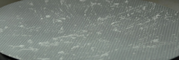
After the salting, I applied a few coats of various shades of grey paint. Then I rubbed some of the salt off, exposing the bright metal underneath. Being that this was the first time I tried this technique, I found that I had probably used a bit much salt, making my chips very large and very numerous. So, I left some of the salt on there and then airbrushed a few light coats of more grey paint over the newly-exposed metal areas. This dulled them down a bit, and added some depth. Next I masked and sprayed a white line across the floor, just for visual interest. Finally, I rubbed off the last little bits of salt, leaving a few fresh paint chips. As an added touch, I took a fine grain sanding stick and gave the surface a very light sanding. As I had hoped, this took the grey paint off of the raised areas, but didn't get down to the metal paint, because of the thick coats of clear in between. This gave me the look of having the grey paint rubbed off of all of the raised parts of the diamond plate.
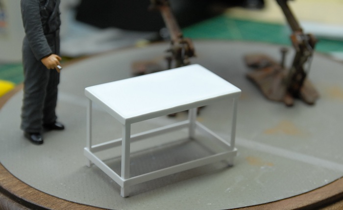
Next up was to build a few extra bits of furniture in order to help fill out the scene. I figured that a little work table would make sense, so I put one together using some strip and sheet styrene that I had around. Below you can see the completed, but unpainted, table in place as I tried to figure out where things should be situated on the base.
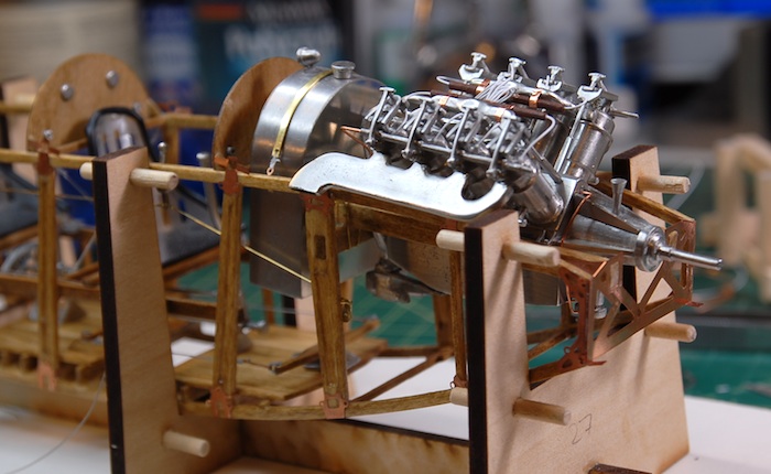
After the table, I noticed that the figure would be far too short to reach the open access panel of the machine without some sort of stool or ladder. So, using the same sort of strip and sheet styrene, I built a little ladder to lean against the side of the model (although I forgot to take a photo of it). This just left a bit of painting on the new parts and weathering of all parts. Below you can see part of my collection of pigments and oil paints that were used for the weathering and detailing. You can also see the couple of doll house props that I bought to go along with this (oil can, lunch box)
That's it for this entry. Up next: photos of the finished model and diorama. Thanks for reading!
Starting with the floor, as I mentioned in the last post, I painted it all a metal color and gave it a few thick coats of clear to protect the metal paint. Next, I decided to try out a new technique: using salt and water to roughly mask coats of paint. This involved dampening the surface and sprinkling table salt over it. The water made the salt stick and I pushed it around a bit with my finger to get it to clump together a bit. Once allowed to dry, the salt hardens up and is ready for painting. Below, you can see my freshly salted floor.
After the salting, I applied a few coats of various shades of grey paint. Then I rubbed some of the salt off, exposing the bright metal underneath. Being that this was the first time I tried this technique, I found that I had probably used a bit much salt, making my chips very large and very numerous. So, I left some of the salt on there and then airbrushed a few light coats of more grey paint over the newly-exposed metal areas. This dulled them down a bit, and added some depth. Next I masked and sprayed a white line across the floor, just for visual interest. Finally, I rubbed off the last little bits of salt, leaving a few fresh paint chips. As an added touch, I took a fine grain sanding stick and gave the surface a very light sanding. As I had hoped, this took the grey paint off of the raised areas, but didn't get down to the metal paint, because of the thick coats of clear in between. This gave me the look of having the grey paint rubbed off of all of the raised parts of the diamond plate.
Next up was to build a few extra bits of furniture in order to help fill out the scene. I figured that a little work table would make sense, so I put one together using some strip and sheet styrene that I had around. Below you can see the completed, but unpainted, table in place as I tried to figure out where things should be situated on the base.
After the table, I noticed that the figure would be far too short to reach the open access panel of the machine without some sort of stool or ladder. So, using the same sort of strip and sheet styrene, I built a little ladder to lean against the side of the model (although I forgot to take a photo of it). This just left a bit of painting on the new parts and weathering of all parts. Below you can see part of my collection of pigments and oil paints that were used for the weathering and detailing. You can also see the couple of doll house props that I bought to go along with this (oil can, lunch box)
That's it for this entry. Up next: photos of the finished model and diorama. Thanks for reading!
Maschinen Krieger - Kröte
28 - May - 2012 - 21:58
After a year spent with the Curtiss Jenny and all of its wood, metal and string, I was definitely ready for a change of pace. I have had this model sitting in my collection for a bunch of years. I bought it a while back, had started working on it, but for whatever reason, ended up boxing it back up.
Part of the Maschinen Krieger series, the model is a mixture of WWII armor and sci-fi designs. This particular model is a bipedal walking tank design, and comes with a figure as well.
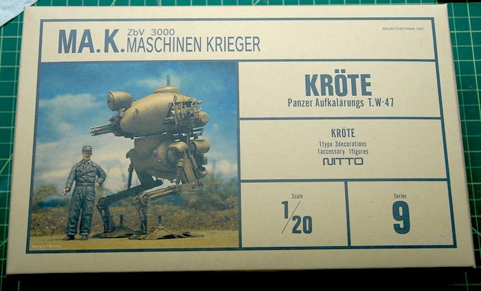
Beginning construction, the upper hull consists of four main parts. The fit wasn't as precise as I would prefer, so there were a few rounds of fitting, gluing, filling, sanding, etc, in order to make it look like one solid part. In the picture below, you can see the main parts assembled. In the front gun area, I added some sheet styrene (where the dark filler is, in the photo), as the kit just let the insides of that area open, which I thought looked a bit odd. The lower hull is just two main left and right halves, which you can see below. The upper and lower sections just twist together and are left unglued.
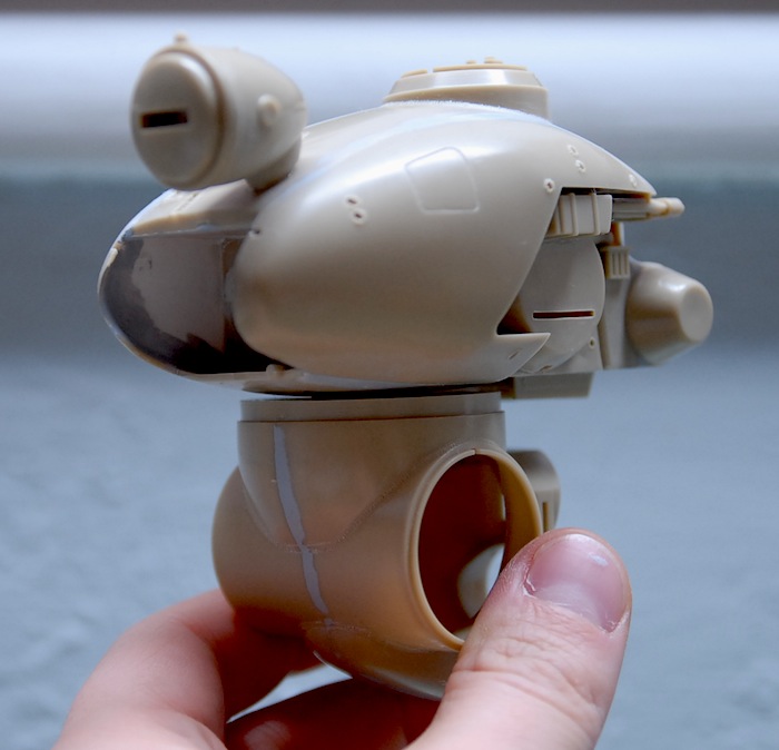
One of the few upgrades/changes I decided to make on this project, was to add a bit of detail to the side panels of the upper hull. As you can see in the image below, the uppoer hull had a recessed area with some cursory detail molded in.
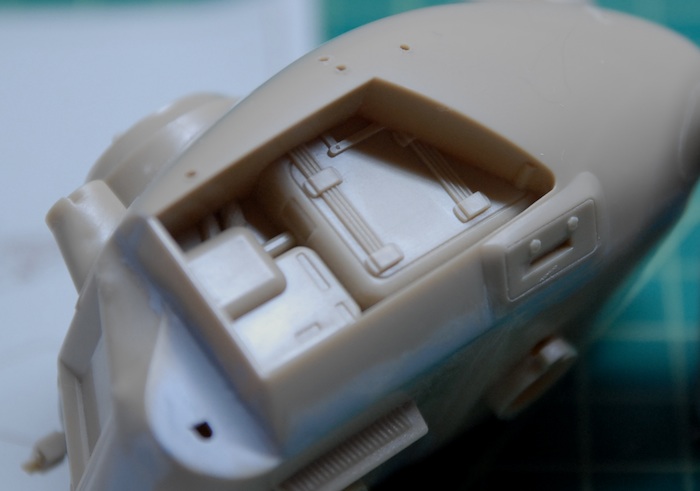
The kit instructions just called for covering that recess with a panel (molded to look like two panels) and going on about your merry way.
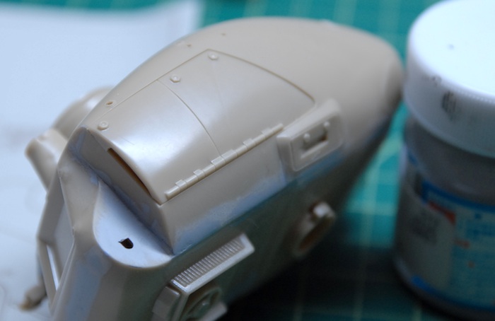
At this point, I thought it might be fun to set this up as a little diorama, making it look like the figure was taking a little break from some repair work on the machine. The first step in this plan was to make these side hatches be opened instead of closed and then add a bit of detail in there. First, I cut the hatch in half, so I could have the two parts be opened a slightly different amount. Next, using some sheet styrene and some shallow U-shaped styrene strip, I added some reinforcement to the back side of the doors.
Along with a few left over parts from previous models, some more strip styrene and some soft copper wire, more detail was added. Finally, the hinges on the hatches were carved a bit (added detail to the side that we now see), and then the panels were glued in place.
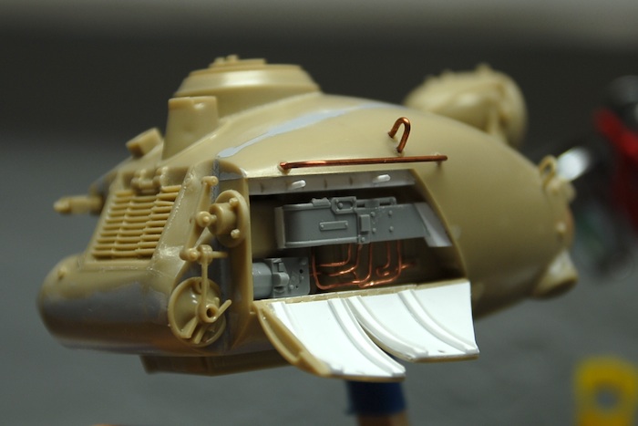
Below you can see all of the various hull subassemblies ready for priming.
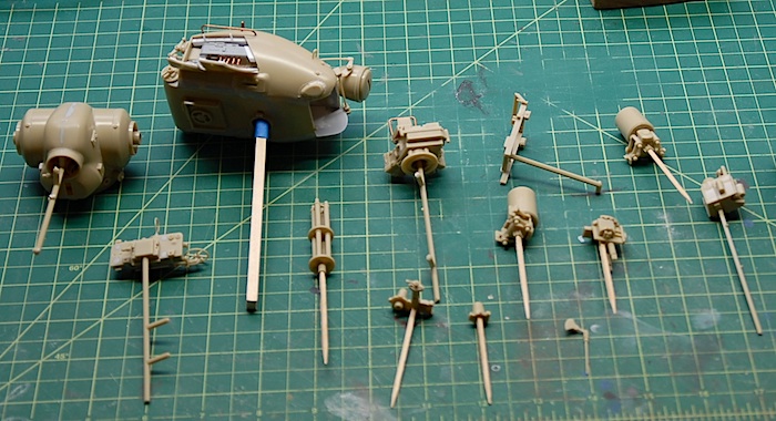
One of my new acquisitions, is this indoor spray booth. It has a vent hose that can be fished out of a window, so that the outside world can enjoy my paint fumes (after running through that blue filter), and it also collapses down into a small-suitcase size, so it can be tucked into the closet as needed.
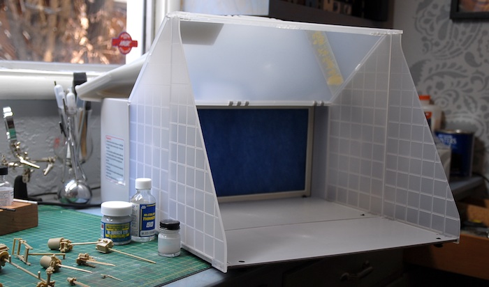
Below you can see the main parts all primed up and ready for another pass at sanding and smoothing seams.
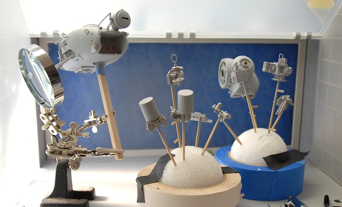
While this was going on, I also assembled the figure and had a shot at painting him. I haven't done any figure painting since I was a kid, so this was somewhat new for me. I stocked up on Vallejo paints before starting, since I had read various mentions of them being great for hand-brushing. I had long been disappointed with the Tamiya paints performance when hand brushing, and found the Vallejo paints to be a welcome change.
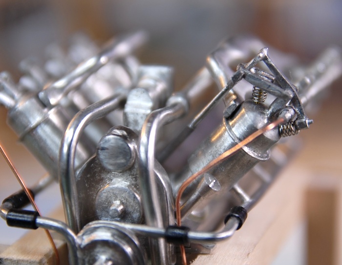
After a pass at painting the main parts, I assembled everything for the upper hull. Next was a pass at rough shading with a darker shade of green and some dry-brushing to highlight the details. A few decals went on and then one more pass with the green paint in order to blend them in a little bit. Below you can see the current state of the top and bottom halves. I have still yet to do a weathering pass, to get things feeling a little more natural. I'm also looking to come up with another decal or two for the inside of the hatches, which would involve some Photoshop work and printing out the images on to decal paper.
Upper hull:
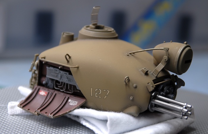
Lower hull and legs:
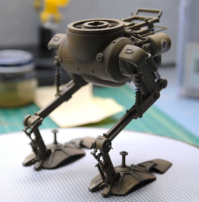
The beginnings of the base for the little diorama can be seen below. I got a wooden oval from a craft store, and stained it. This was followed by a few coats of polyurethane. I ran across some diamond plate styrene sheet at the hobby store and though that might make a good hanger floor. So far it has just gotten a few coats of Testor's metalizer paint, soon to be followed by some yellow markings and some grey to dull it all down.
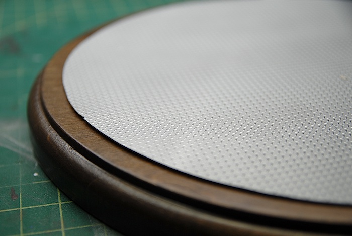
That's all for now. More updates to follow as this project wraps up!
Part of the Maschinen Krieger series, the model is a mixture of WWII armor and sci-fi designs. This particular model is a bipedal walking tank design, and comes with a figure as well.
Beginning construction, the upper hull consists of four main parts. The fit wasn't as precise as I would prefer, so there were a few rounds of fitting, gluing, filling, sanding, etc, in order to make it look like one solid part. In the picture below, you can see the main parts assembled. In the front gun area, I added some sheet styrene (where the dark filler is, in the photo), as the kit just let the insides of that area open, which I thought looked a bit odd. The lower hull is just two main left and right halves, which you can see below. The upper and lower sections just twist together and are left unglued.
One of the few upgrades/changes I decided to make on this project, was to add a bit of detail to the side panels of the upper hull. As you can see in the image below, the uppoer hull had a recessed area with some cursory detail molded in.
The kit instructions just called for covering that recess with a panel (molded to look like two panels) and going on about your merry way.
At this point, I thought it might be fun to set this up as a little diorama, making it look like the figure was taking a little break from some repair work on the machine. The first step in this plan was to make these side hatches be opened instead of closed and then add a bit of detail in there. First, I cut the hatch in half, so I could have the two parts be opened a slightly different amount. Next, using some sheet styrene and some shallow U-shaped styrene strip, I added some reinforcement to the back side of the doors.
Along with a few left over parts from previous models, some more strip styrene and some soft copper wire, more detail was added. Finally, the hinges on the hatches were carved a bit (added detail to the side that we now see), and then the panels were glued in place.
Below you can see all of the various hull subassemblies ready for priming.
One of my new acquisitions, is this indoor spray booth. It has a vent hose that can be fished out of a window, so that the outside world can enjoy my paint fumes (after running through that blue filter), and it also collapses down into a small-suitcase size, so it can be tucked into the closet as needed.
Below you can see the main parts all primed up and ready for another pass at sanding and smoothing seams.
While this was going on, I also assembled the figure and had a shot at painting him. I haven't done any figure painting since I was a kid, so this was somewhat new for me. I stocked up on Vallejo paints before starting, since I had read various mentions of them being great for hand-brushing. I had long been disappointed with the Tamiya paints performance when hand brushing, and found the Vallejo paints to be a welcome change.
After a pass at painting the main parts, I assembled everything for the upper hull. Next was a pass at rough shading with a darker shade of green and some dry-brushing to highlight the details. A few decals went on and then one more pass with the green paint in order to blend them in a little bit. Below you can see the current state of the top and bottom halves. I have still yet to do a weathering pass, to get things feeling a little more natural. I'm also looking to come up with another decal or two for the inside of the hatches, which would involve some Photoshop work and printing out the images on to decal paper.
Upper hull:
Lower hull and legs:
The beginnings of the base for the little diorama can be seen below. I got a wooden oval from a craft store, and stained it. This was followed by a few coats of polyurethane. I ran across some diamond plate styrene sheet at the hobby store and though that might make a good hanger floor. So far it has just gotten a few coats of Testor's metalizer paint, soon to be followed by some yellow markings and some grey to dull it all down.
That's all for now. More updates to follow as this project wraps up!
GT-R Complete & Photos
08 - August - 2010 - 10:07
I've wrapped up the build of the Tamiya GT-R kit. By the time I was finishing up this kit, I was remembering why is was that I tried a wooden kit in the first place. I get worn out on all the painting, the frustrations of various paint types not agreeing with one another, and the fragility of decals. Although at least with this project, I took away a few valuable lessons that I can keep in mind for future similar projects. Here are a few tidbits to remember:
- If it is going to be shiny, use lacquer. Tamiya's gloss acrylics just never behave when airbrushed.
- Don't use the microSOL (aka Decal Melter) until the decal is in it's final place and already partly dry.
- If some of it will be painted over, remove the underlying chrome plating first, otherwise, the paint will just chip off, despite using primer.
- Give the aforementioned lacquer PLENTY of time to dry before putting masking tape on it. Probably should wait 24 hours before trying.
- One should probably order a second set of decals for a project like this, as some are sure to be damaged. Alternately, perhaps one could scan them, and buy a self-print decal sheet so one could make replacements (although I'm not sure about the quality difference here)
- Third party racing harness kits, while pretty cool, might not be worth the effort unless the car is an open wheel type.
Anyhow, with this project completed, I spent a few minutes photographing but this car and the last project (WWII BMW r75 motorcycle). I recently purchased a new lens, which has some macro capabilities, and tried that out on this shoot. I am pretty pleased with the results. Here are a few images of the completed models:
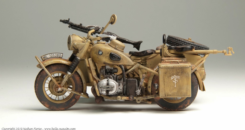
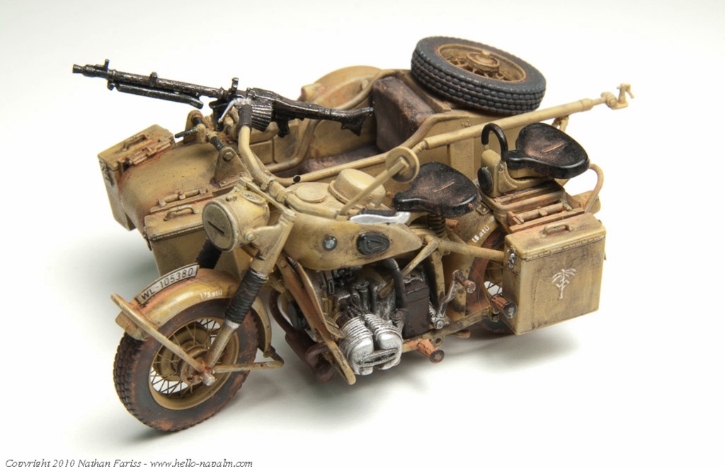
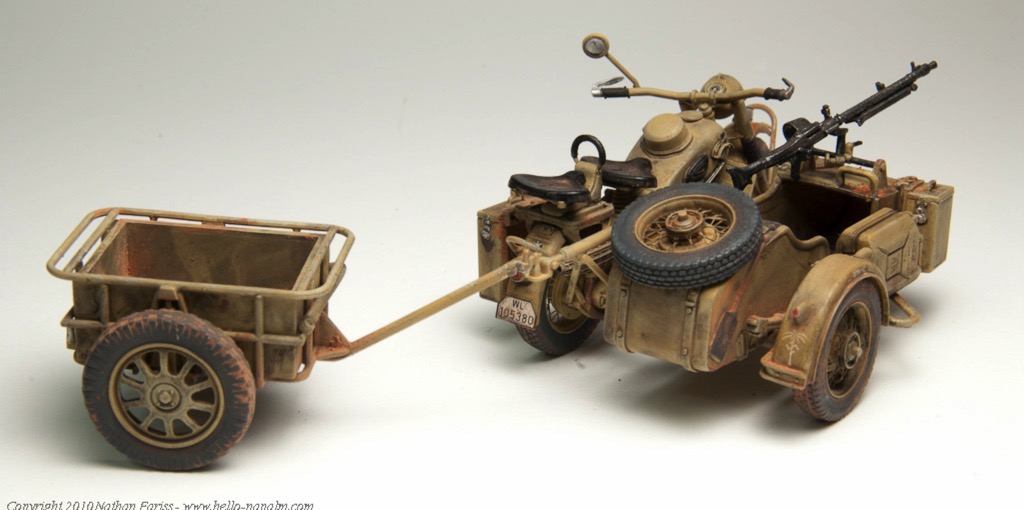
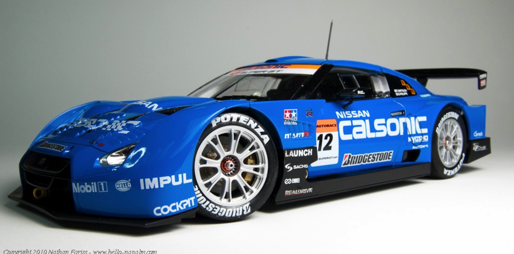
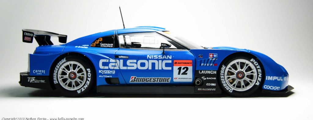
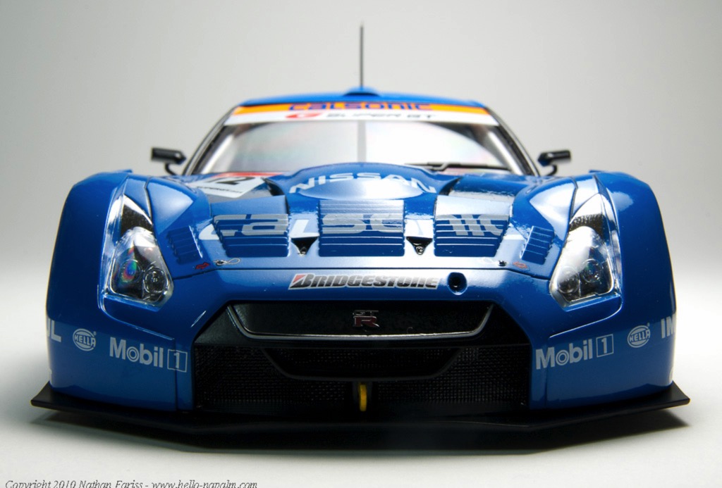
The full galleries are online and can be seen in the completed models section of this web site.
Next up: Model Airways' Curtis 'Jenny' wooden plane. Stay tuned for more model adventures!
- If it is going to be shiny, use lacquer. Tamiya's gloss acrylics just never behave when airbrushed.
- Don't use the microSOL (aka Decal Melter) until the decal is in it's final place and already partly dry.
- If some of it will be painted over, remove the underlying chrome plating first, otherwise, the paint will just chip off, despite using primer.
- Give the aforementioned lacquer PLENTY of time to dry before putting masking tape on it. Probably should wait 24 hours before trying.
- One should probably order a second set of decals for a project like this, as some are sure to be damaged. Alternately, perhaps one could scan them, and buy a self-print decal sheet so one could make replacements (although I'm not sure about the quality difference here)
- Third party racing harness kits, while pretty cool, might not be worth the effort unless the car is an open wheel type.
Anyhow, with this project completed, I spent a few minutes photographing but this car and the last project (WWII BMW r75 motorcycle). I recently purchased a new lens, which has some macro capabilities, and tried that out on this shoot. I am pretty pleased with the results. Here are a few images of the completed models:
The full galleries are online and can be seen in the completed models section of this web site.
Next up: Model Airways' Curtis 'Jenny' wooden plane. Stay tuned for more model adventures!
Model Desk Renovation & Tamiya GT-R
05 - July - 2010 - 17:18
Since the last post, I've done a few things to make my workspace a bit better.
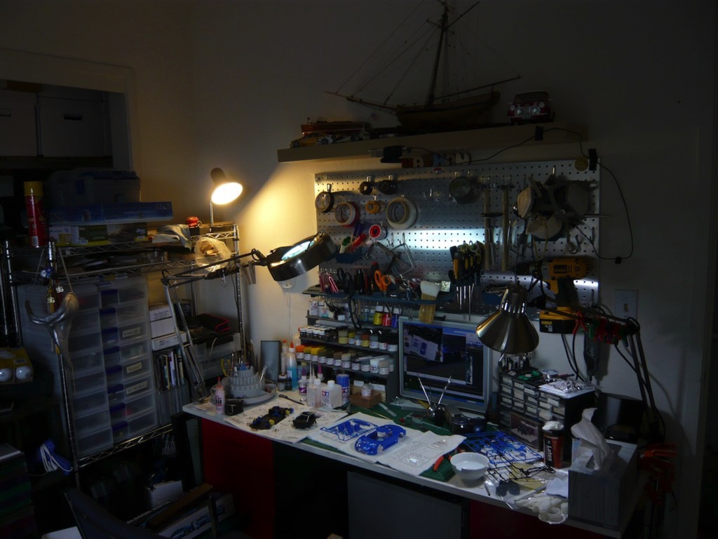
First I built myself a little shelf, so that I could have better access to my various paints, glues and other toxic chemicals. I just picked up a small sheet of thin plywood at Home Depot as well as some little 1"x1"x12" blocks of pine. I worked up some quick plans, drew them out onto the plywood, busted out the jigsaw and started cutting. After some gluing, drilling, a few wood screws, and a couple coats of gray spray paint, I now have a nice little shelf for my desk (you can also see here the monitor for the cam/computer setup I mentioned in the previous post):
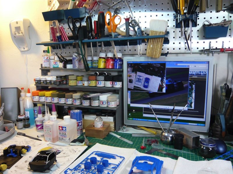
Next, after knocking over my bottle of high-power plastic cement, and melting all the lines off the middle of my cutting mat, I thought it might be a good idea to make sure that doesn't happen again. Especially since this was not the first time I had knocked this same bottle over. After rummaging around a bit, I found some nice wood I had left over from the base I made for the Panzer project (red oak, I think). I cut a couple squares of this, glued them together, and then, using a hole saw, drilled a hole just a bit bigger than the glue bottle. A couple coats of polyurethane, and now I've got a little block that keeps my glue bottle from falling over and doesn't look too terrible.
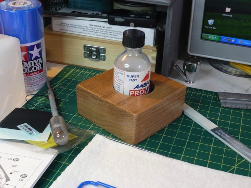
Before I jumped into another long-term wooden project, I decided to make one more plastic kit. I settled on the Tamiya Calsonic Impul GT-R kit that I bought a while back, thinking it would be fairly quick and easy, since it doesn't have an engine and only a rudimentary interior. I had intended to build it straight from the box, but I couldn't resist adding an third party racing harness kit. Here you can see the completed interior, as well as the mostly-built exterior shell:
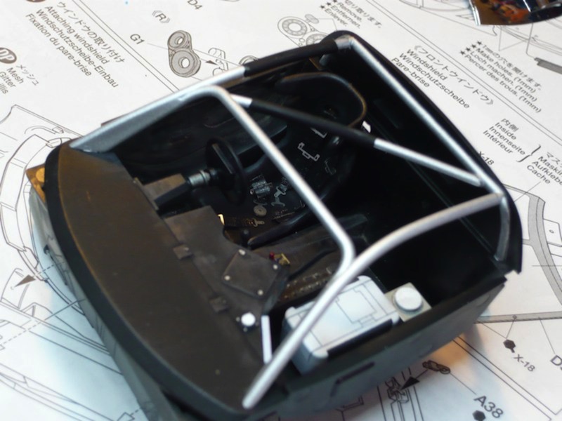
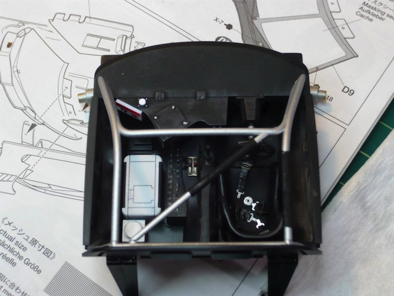
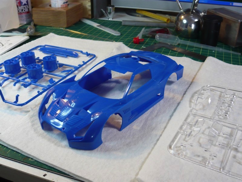
I should wrap this project up in the next few weeks, and then I'll get some proper photographs of both this completed model and the motorcycle model that I finished before this one. Stay tuned!
First I built myself a little shelf, so that I could have better access to my various paints, glues and other toxic chemicals. I just picked up a small sheet of thin plywood at Home Depot as well as some little 1"x1"x12" blocks of pine. I worked up some quick plans, drew them out onto the plywood, busted out the jigsaw and started cutting. After some gluing, drilling, a few wood screws, and a couple coats of gray spray paint, I now have a nice little shelf for my desk (you can also see here the monitor for the cam/computer setup I mentioned in the previous post):
Next, after knocking over my bottle of high-power plastic cement, and melting all the lines off the middle of my cutting mat, I thought it might be a good idea to make sure that doesn't happen again. Especially since this was not the first time I had knocked this same bottle over. After rummaging around a bit, I found some nice wood I had left over from the base I made for the Panzer project (red oak, I think). I cut a couple squares of this, glued them together, and then, using a hole saw, drilled a hole just a bit bigger than the glue bottle. A couple coats of polyurethane, and now I've got a little block that keeps my glue bottle from falling over and doesn't look too terrible.
Before I jumped into another long-term wooden project, I decided to make one more plastic kit. I settled on the Tamiya Calsonic Impul GT-R kit that I bought a while back, thinking it would be fairly quick and easy, since it doesn't have an engine and only a rudimentary interior. I had intended to build it straight from the box, but I couldn't resist adding an third party racing harness kit. Here you can see the completed interior, as well as the mostly-built exterior shell:
I should wrap this project up in the next few weeks, and then I'll get some proper photographs of both this completed model and the motorcycle model that I finished before this one. Stay tuned!
A Sneak Preview
19 - June - 2010 - 08:22
Just a quick post to bring things up to date. Here's a quick look at upcoming projects.
This past week I received a kit for another wooden and metal model. This one is a WWI biplane, the Curtiss JN-4D 'Jenny'. I'm hoping that it'll be a challenging build, similar to the Sloop build, except with much more metal and photo-etch. I'm actually hoping to set up a time-lapse recording method for this build, using an old computer, and a webcam. But since I think this might take me a little bit to get set up and tested, I'm going to hold off on starting this build for a little while.
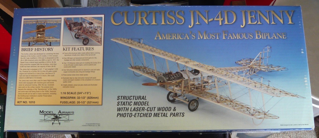
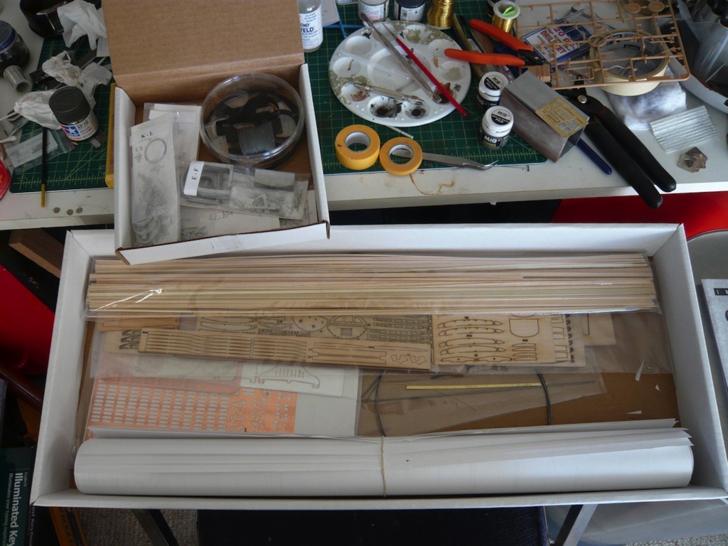
So, in the meantime, after wrapping up the motorcycle model (which I plan on doing today), I'll be putting this one together:
It should be a quick, fun build, since there isn't any engine. I was in the mood to make something shiny before I start on a longer build, so I figure I can crank through this one in a few weeks, and should be able to test out my time-lapse setup in the process :)
And there we have it. That's my modeling progress brought up to date. Party on.
This past week I received a kit for another wooden and metal model. This one is a WWI biplane, the Curtiss JN-4D 'Jenny'. I'm hoping that it'll be a challenging build, similar to the Sloop build, except with much more metal and photo-etch. I'm actually hoping to set up a time-lapse recording method for this build, using an old computer, and a webcam. But since I think this might take me a little bit to get set up and tested, I'm going to hold off on starting this build for a little while.
So, in the meantime, after wrapping up the motorcycle model (which I plan on doing today), I'll be putting this one together:
It should be a quick, fun build, since there isn't any engine. I was in the mood to make something shiny before I start on a longer build, so I figure I can crank through this one in a few weeks, and should be able to test out my time-lapse setup in the process :)
And there we have it. That's my modeling progress brought up to date. Party on.
And Moving Right Along....
19 - June - 2010 - 08:00
I didn't rest long after wrapping up the Panzer. I jumped right into another vehicle of the same era and same scale. This kit is a BMW R75, manufactured by Lions Roar. I'm not adding any after market parts to this one, but it comes with quite a bit of detail out of the box. It's got a variety of photo-etched parts for the wheel spokes, various engine bits and for a few other small details, like the padlocks on equipment boxes. The kit also comes with a sidecar and two versions of a little trailer.
The build was pretty straightforward, with the exception of things just being very very small. The motorcycle is the same scale as the last tank model I built, at 1/35 scale. This makes the whole bike only a few inches long. As you can see from the photos below, there is a pretty good amount of detail in the kit. Also, overall the quality of the kit modeling, while pretty good, was not quite as good as the Panzer kit (which was made by Dragon), so required a good deal more cleanup of mold seams, etc. With the parts being as tiny as they were, this cleanup occasionally resulted in broken parts. This also led me to be fairly certain that I like working on larger models :)
I'm currently working on wrapping this project up, with weathering powders, etc, but as it's not quite done, here are a few photos of the model as of last weekend. My hope for this one is to combine it with the Panzer for display, so that I can put them both on the same wooden base. This just means that I've got to be sure they generally match color-wise and look like they've been living in the same world.
Assembled in sections, engine masked for painting the body.
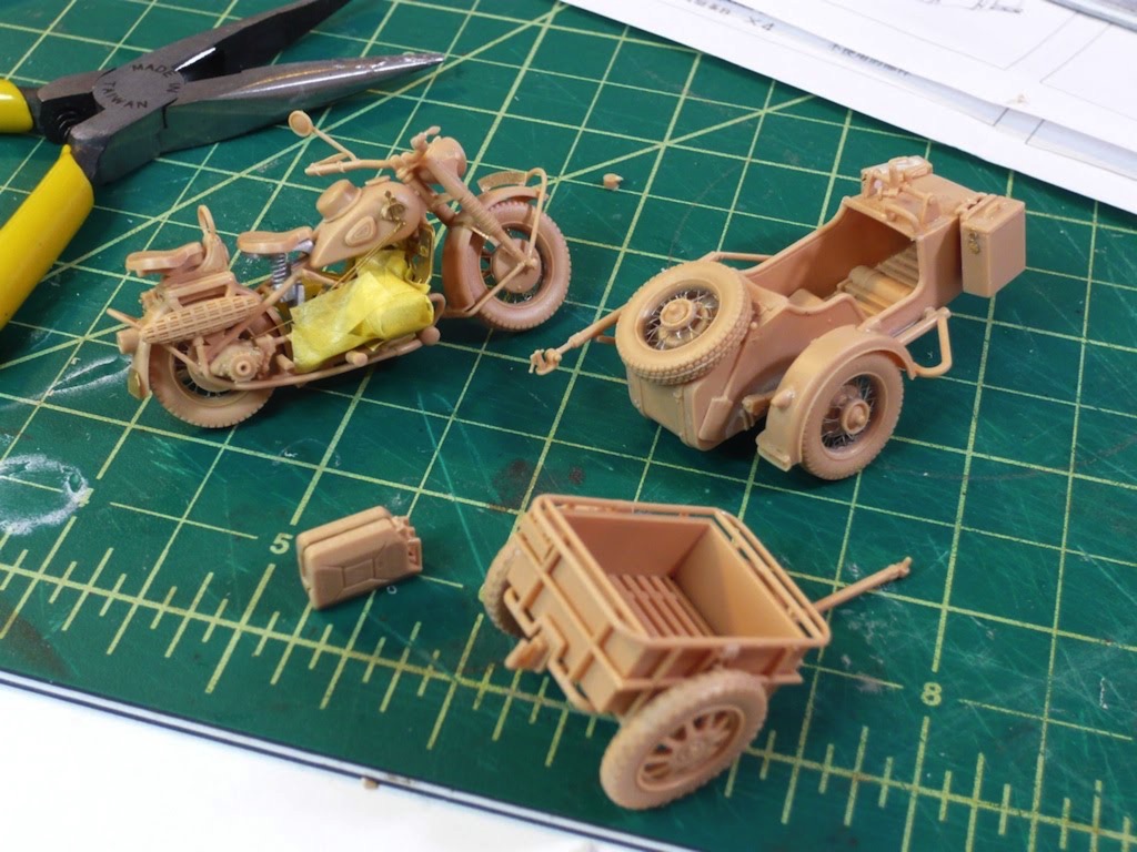
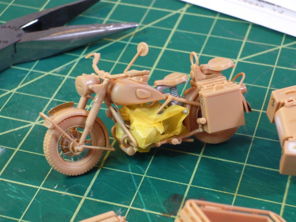
After a base coat of dark yellow.
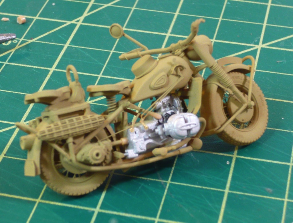
The build was pretty straightforward, with the exception of things just being very very small. The motorcycle is the same scale as the last tank model I built, at 1/35 scale. This makes the whole bike only a few inches long. As you can see from the photos below, there is a pretty good amount of detail in the kit. Also, overall the quality of the kit modeling, while pretty good, was not quite as good as the Panzer kit (which was made by Dragon), so required a good deal more cleanup of mold seams, etc. With the parts being as tiny as they were, this cleanup occasionally resulted in broken parts. This also led me to be fairly certain that I like working on larger models :)
I'm currently working on wrapping this project up, with weathering powders, etc, but as it's not quite done, here are a few photos of the model as of last weekend. My hope for this one is to combine it with the Panzer for display, so that I can put them both on the same wooden base. This just means that I've got to be sure they generally match color-wise and look like they've been living in the same world.
Assembled in sections, engine masked for painting the body.
After a base coat of dark yellow.
Looooooong Overdue Update...
19 - June - 2010 - 07:28
So, yes, I realize I became one of those people that starts up a blog with all the intentions of keeping it updated, and then fell behind. But now I'm back and I've got a bunch of updates!
First and foremost, I've finished the Panzer III and have some photos of the finished project. I forgot to take photos of the outside, as I was putting everything together, so I really just have the images of the finished model. Everything on the outside was pretty straight forward, without all the complicated resin construction that the interior had.
The difficult bits of the exterior were really just the assembly of the individual-link plastic tracks and then the final assembly and weathering of the whole tank. I managed to get the tracks assembled by sticking the track links to a strip of thin masking tape, then draping that over the various wheels, and once in place, dabbing glue to where the tracks touch one another. I found that I could make each side in four or so sections, which still allowed me to take the tracks back off, paint them, and then, once the rest of the tank was painted, put the tracks back on again.
The painting was simply an airbrushed coat of dark yellow on most of the exterior, with a few of the detail parts picked out in other colors by hand. The road wheels were originally painted in German Grey, and then, using a plastic circle template as a mask, the centers were sprayed the same dark yellow as the rest of the tank. After the base coats were complete, I sprayed a slightly darker yellow into the nooks, crannies and corners to get a bit of shading. This was followed by a pass of drybrushing with a light tan to help pick out corners, details and texture.
Next came an extensive application of Mig Pigments. These are just colored powders, that get dusted onto the surface and then a bit of thinner is touched to the powder, and that helps it stick to the surface and flow into the texture of the surface and in between details. This serves to both further pick out detail when using a darker color pigment, and also to add dirt and grime when using lighter tones.
Once that was done, I cut a chunk of red oak for a base, put a few coats polyurethane on that and called it done! Since then, I have grown less happy with the base, feeling that it needed to better contrast with the model, so stay tuned for an update on that.
Here are a few images of the completed model, but see the completed models section of this web site for more.
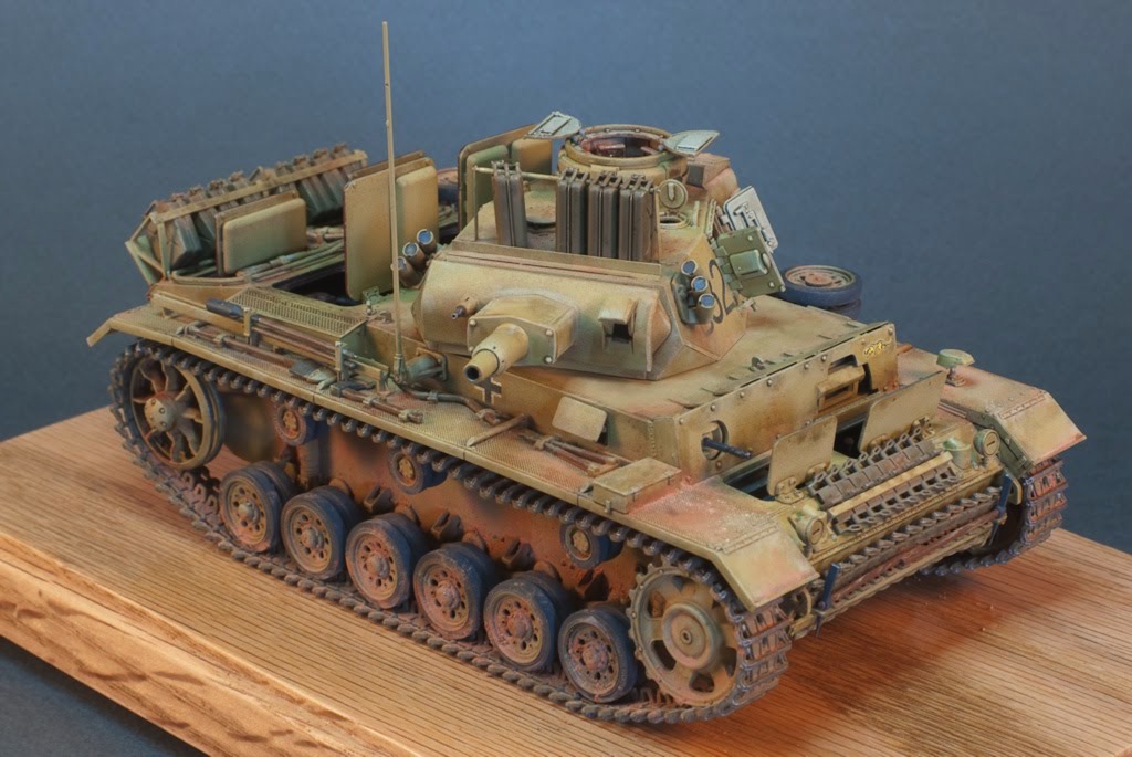
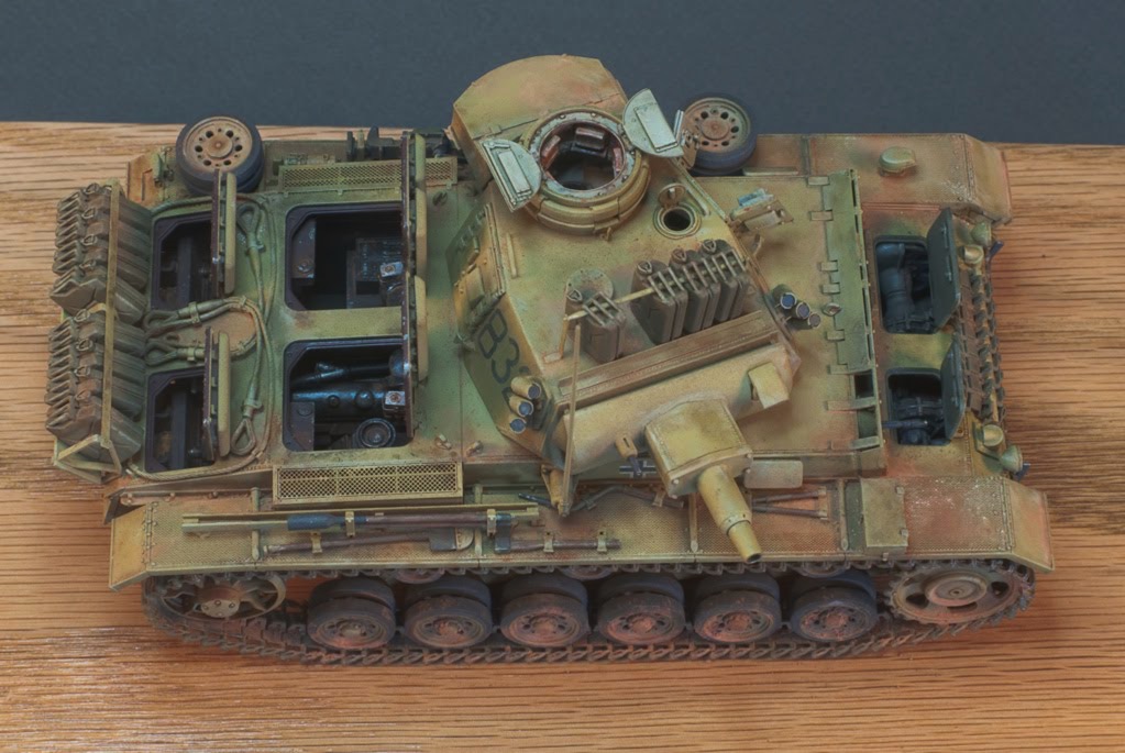
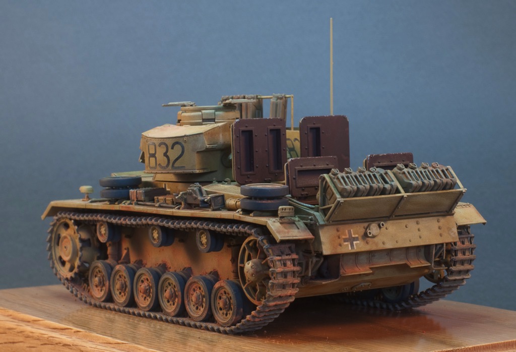
Panzer III Interior Paint
13 - February - 2010 - 09:10
With the interior build pretty much complete, I moved on to added a bit of paint. From what I could gather, the Germans painted everything in a red primer and left it that way for non-crew areas and painted all the crew areas in a dull grey-green.
I began by airbrushing the whole interior with Mr Surfacer 1200 as a primer and to give it all a uniform color. Next I sprayed the red-brown color onto the engine compartment and onto the engine and radiator assemblies. I decided to leave the engine and radiator parts separate during the painting and weathering process to make things easier. Finally, I masked the engine area and sprayed the crew cabin in the grey green.
Next I spent a bit of time picking out a few details by hand and adding metallic spots on corners to simulate paint chips. Here you can see a little of that in progress:
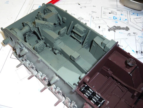
I followed that with a bit of dry brushing using a lighter tone to help pick out the details and raised bits. Next I tried out a technique that is new to me: the use of pigments. Pigment is the raw color component of many paints (although in a non-toxic version). I ordered a few sets of Mig Pigments from an online hobby store (since I have never seen more than a few jars locally), and now I've got 12 shades of rust, dirt, smoke and ash to choose from.
The jist of the pigments is that you sort of just use a dry brush to apply a variety of colors here and there, and then wet everything down with a thinner and use that to blend between colors and get the solution into all the cracks and crevices. I started out with a wash of black to help add contrast and pick out the details, and then followed up with various dirt and rust colors. I generally found it very easy to work with and I am quite pleased with the results.
A few images of paint and weathering (with the pigments):
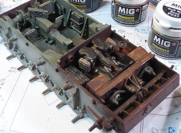
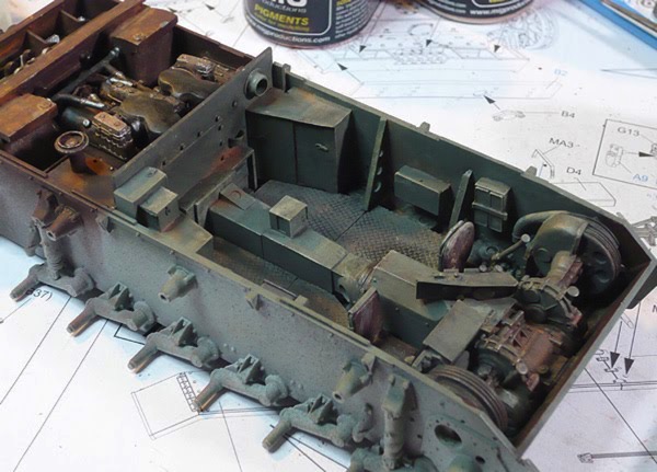
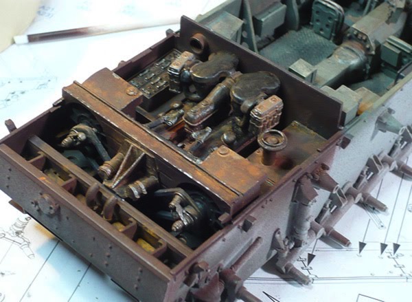
That pretty much wraps up the interior. There are a few odds and ends to take care of, like cementing the engine parts in place and connecting a few things with pipes. I'm sure there will also be a bit of work going into the upper hull build as well, but that is all for a later post.
Next: Onward with the construction!
I began by airbrushing the whole interior with Mr Surfacer 1200 as a primer and to give it all a uniform color. Next I sprayed the red-brown color onto the engine compartment and onto the engine and radiator assemblies. I decided to leave the engine and radiator parts separate during the painting and weathering process to make things easier. Finally, I masked the engine area and sprayed the crew cabin in the grey green.
Next I spent a bit of time picking out a few details by hand and adding metallic spots on corners to simulate paint chips. Here you can see a little of that in progress:
I followed that with a bit of dry brushing using a lighter tone to help pick out the details and raised bits. Next I tried out a technique that is new to me: the use of pigments. Pigment is the raw color component of many paints (although in a non-toxic version). I ordered a few sets of Mig Pigments from an online hobby store (since I have never seen more than a few jars locally), and now I've got 12 shades of rust, dirt, smoke and ash to choose from.
The jist of the pigments is that you sort of just use a dry brush to apply a variety of colors here and there, and then wet everything down with a thinner and use that to blend between colors and get the solution into all the cracks and crevices. I started out with a wash of black to help add contrast and pick out the details, and then followed up with various dirt and rust colors. I generally found it very easy to work with and I am quite pleased with the results.
A few images of paint and weathering (with the pigments):
That pretty much wraps up the interior. There are a few odds and ends to take care of, like cementing the engine parts in place and connecting a few things with pipes. I'm sure there will also be a bit of work going into the upper hull build as well, but that is all for a later post.
Next: Onward with the construction!
Panzer III Interior Build
13 - February - 2010 - 08:50
So, it's been quite a while since I've updated so I've going to break this into two posts: one on the build and one about painting and weathering. First, the build:
I purchased resin interior and engine kits made by Verlinden. The interior kit was designed for a Tamiya version of the same tank, while the engine claimed it would fit both Tamiya and Dragon kits. When I got in there and slowly started piecing things together I discovered a few things:
First off, I'm not that crazy about working with large resin parts. There seems to be a ton of work to do just to get the part somewhere close to where it should be, since one needs to sand off a great deal of the overpour. There also seems to be a tendency of the large flat resin parts to warp a bit with the heat of sanding. I suppose these are things to learn about working with resin, and they will inform my future projects, but I just came away with the impression that resin is just plain less fun to work with compared to plastic or wood.
Next thing I learned was that the Tamiya version of the kit must not have all of the interior suspension parts that the Dragon kit does, as the resin parts had all of the same part cast into the floor of the interior. This gave me two options: cut away all the Dragon interior parts or cut away the resin parts. Since I thought the kit parts looked better than the resin parts, I opted for what was probably the hardest route, and decided to cut away the whole floor of the resin parts and replace it with a new version.
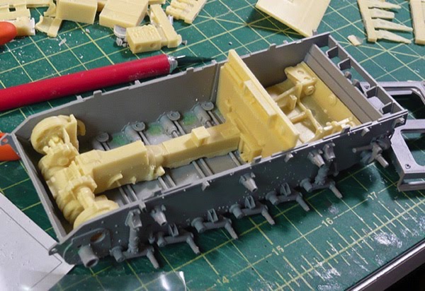
In retrospect, a closer inspection of some reference photos could have saved me some trouble. I started with the impression that the floor inside the tank was a metal mesh, similar to what one would find on catwalks and other industrial settings. So I cut away all the floor, and found some fine screen, with the intention of using the screen for the floor to simulate the grating. This would allow the fancy suspension bit to be seen through the floor just a little bit. Later on, in my quest for find proper paint colors, I ran across some photos of a restored Panzer and it had flooring made of diamond plate, which is quite opaque. So, instead of the screen idea and instead of trying to find some scale diamond plate, I took some styrene sheet, heated it with a cooking torch (like for making creme brulee) and pressed the screen from a cooking splatter guard into it to form a criss-cross pattern that is similar to diamond plate.
Finally, I learned that the interior and engine kits both came with a firewall to go between. Once all the parts for the interior and exterior are in place, without any firewalls, they take up pretty much the whole interior, leaving not enough room for EITHER firewall. So, what I ended up having to do is to build a new firewall from scratch from styrene. I tried to get the general shape from both of the resin parts and even clipped off a few of the resin details and added them to the new version. I also found that I had to cut quite a bit off of the bottom of the engine in order to get it to sit low enough in the chassis for the upper hull pieces to be able to attach. This, of course, caused all the pipes to mis-align, so there are still a few things that will need tweaking once paint is done and I am cementing things into the hull.
Some images of the built-up interior and engine:
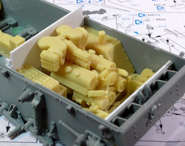
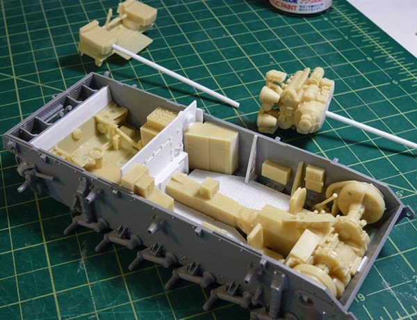
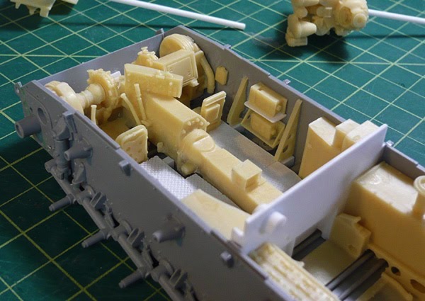
And finally, with a coat of Mr Surfacer 1200 as a primer:
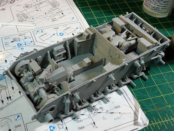
Next: some paint!
I purchased resin interior and engine kits made by Verlinden. The interior kit was designed for a Tamiya version of the same tank, while the engine claimed it would fit both Tamiya and Dragon kits. When I got in there and slowly started piecing things together I discovered a few things:
First off, I'm not that crazy about working with large resin parts. There seems to be a ton of work to do just to get the part somewhere close to where it should be, since one needs to sand off a great deal of the overpour. There also seems to be a tendency of the large flat resin parts to warp a bit with the heat of sanding. I suppose these are things to learn about working with resin, and they will inform my future projects, but I just came away with the impression that resin is just plain less fun to work with compared to plastic or wood.
Next thing I learned was that the Tamiya version of the kit must not have all of the interior suspension parts that the Dragon kit does, as the resin parts had all of the same part cast into the floor of the interior. This gave me two options: cut away all the Dragon interior parts or cut away the resin parts. Since I thought the kit parts looked better than the resin parts, I opted for what was probably the hardest route, and decided to cut away the whole floor of the resin parts and replace it with a new version.
In retrospect, a closer inspection of some reference photos could have saved me some trouble. I started with the impression that the floor inside the tank was a metal mesh, similar to what one would find on catwalks and other industrial settings. So I cut away all the floor, and found some fine screen, with the intention of using the screen for the floor to simulate the grating. This would allow the fancy suspension bit to be seen through the floor just a little bit. Later on, in my quest for find proper paint colors, I ran across some photos of a restored Panzer and it had flooring made of diamond plate, which is quite opaque. So, instead of the screen idea and instead of trying to find some scale diamond plate, I took some styrene sheet, heated it with a cooking torch (like for making creme brulee) and pressed the screen from a cooking splatter guard into it to form a criss-cross pattern that is similar to diamond plate.
Finally, I learned that the interior and engine kits both came with a firewall to go between. Once all the parts for the interior and exterior are in place, without any firewalls, they take up pretty much the whole interior, leaving not enough room for EITHER firewall. So, what I ended up having to do is to build a new firewall from scratch from styrene. I tried to get the general shape from both of the resin parts and even clipped off a few of the resin details and added them to the new version. I also found that I had to cut quite a bit off of the bottom of the engine in order to get it to sit low enough in the chassis for the upper hull pieces to be able to attach. This, of course, caused all the pipes to mis-align, so there are still a few things that will need tweaking once paint is done and I am cementing things into the hull.
Some images of the built-up interior and engine:
And finally, with a coat of Mr Surfacer 1200 as a primer:
Next: some paint!
Next Project! Dragon Panzer III Ausf.N Tank
13 - December - 2009 - 20:21
And now for something completely different...
So, I've begun my next project. I picked a few plastic armor kits up last February, when I stumbled upon a new hobby shop (which has since become my main hobby shop), and found that they were having a sale. I had done a little bit of reading and looked for kits that came with individual-link tracks, and some photo-etched metal parts, in hopes of finding the kits challenging. The one that I am starting with is a German Panzer tank, of a fairly late revision, with markings from their African campaign. This kit is made by Dragon, and they look to have gone above and beyond when it comes to the quality of the plastic molding and overall level of detail.
I've also decided to try quite a few new things on this project. Since I haven't really done any sort of armor model since I was a little kid, I figured I could try lots of new things, based on recent reading and get much of the learning going all at once. First off, I am trying some new paints, primers, and glues. I've picked up some Mr Surfacer products for priming and filling, some Pro Weld plastic welder to replace the Testors cement I've always used, some Milliput epoxy putty, and various super glues, sanding devices, etc, all that I have not tried before. Later in the project, I also hope to experiment with some new airbrushing techniques, and to try out some weathering techniques using pigments and some artist oils.
Here is the kit that I am working with.
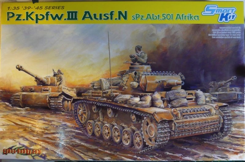
Here's an example of the instructions. They don't seem to be real big on the step-by-step sort of approach and instead seem to go for more of a put-all-this-stuff-together-at-once sorta thing.
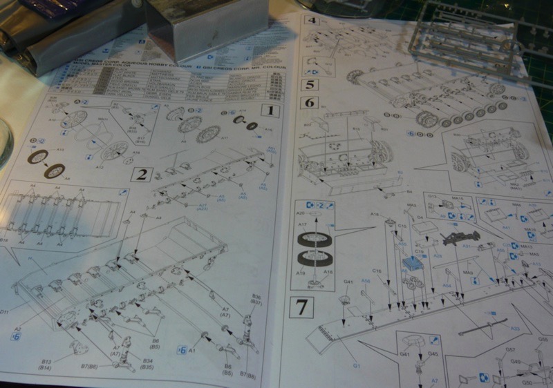
I've started putting a few pieces together. Mostly this has just involved a great deal of sanding and a little filling. I've been trying out filling tiny seams with Mr Surfacer 500, which is somewhere in between primer and filler. It seems to be working pretty well so far, although I've only used it to smooth over some seams on the drive wheels.
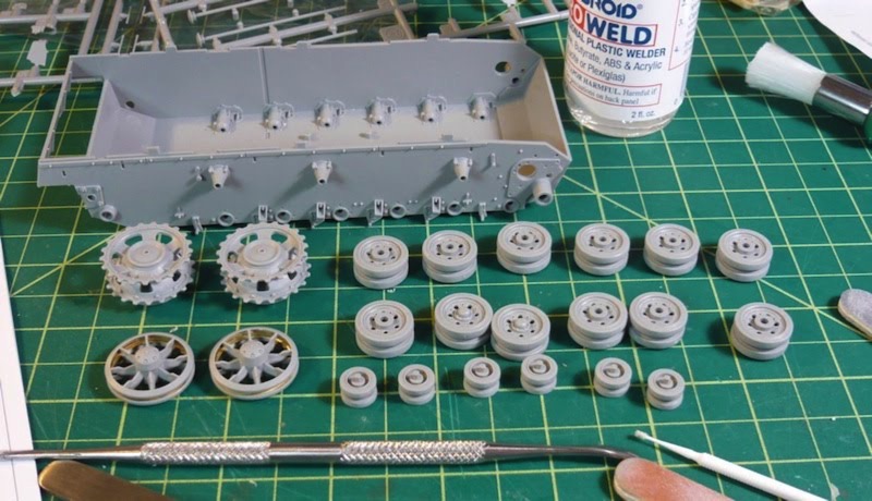
Another in the list of new things I am trying on this kit is the addition of a third-party resin interior kit. The model did not come with any interior parts beyond a few gun parts that go inside the turret. But, the kit DOES allow for all of the hatches and portals to be assembled in an open position. So, with a little scrounging and some sanity checks on the Fine Scale Modeler forums, I decided on an interior kit and an engine bay kit, both from Verlinden. The interior kit adds the various crew-related parts as well as a floor, transmission tunnel and various other transmission parts. The engine bay adds the bits on the other side of the firewall, which is mostly just the engine and some fans and things.
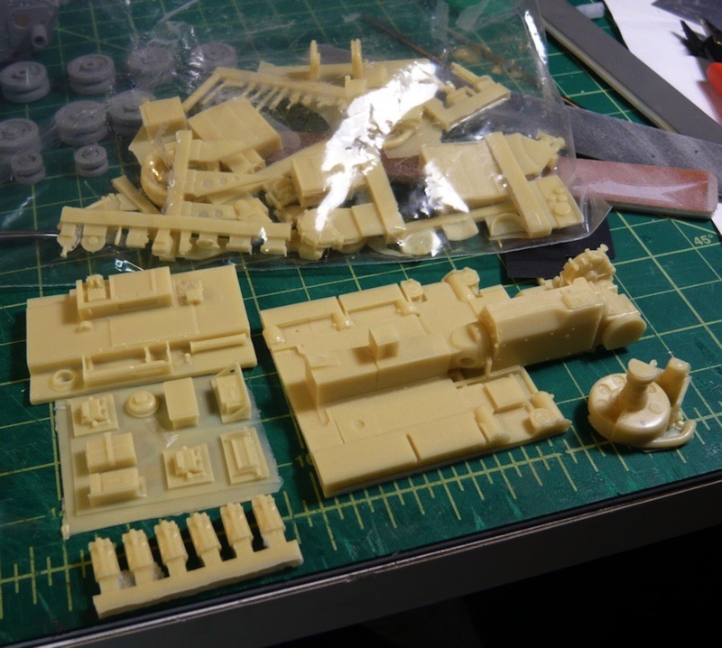
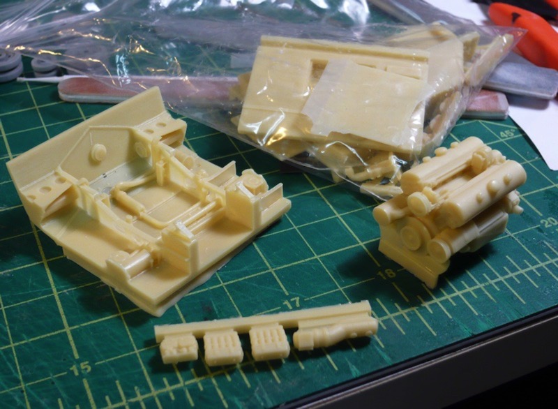
Here is how they roughly fit into the lower hull piece.
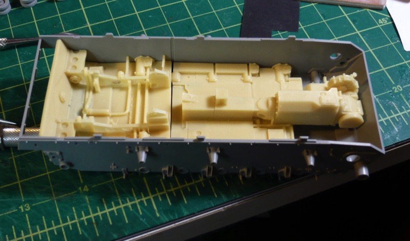
The big catch here, is that these resin bits were not made for this Dragon kit, but rather for a Tamiya kit, which has less internal detail. As a result, there is some duplication in details between the lower hull part of the plastic kit and the detail in the resin kit. This means that this will take a bit of figuring and some quality time with the Dremel in order to get everything to play nicely with one another. Below is an image, with tiny red arrows, illustrating the duplicated details.
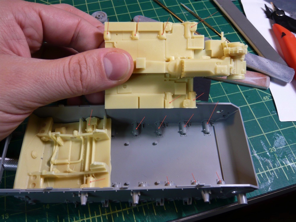
All in all, I am pretty excited about this project, as it is really nice to have a bit of a change of pace after all that time with wood and string and superglue. Stay tuned for further updates as this one progresses, hopefully at a slightly faster pace than the last project. If all goes well, I'm hoping to have this one completed in time to enter into the Hobby Expo 2010 on February 20th, in Petaluma.
So, I've begun my next project. I picked a few plastic armor kits up last February, when I stumbled upon a new hobby shop (which has since become my main hobby shop), and found that they were having a sale. I had done a little bit of reading and looked for kits that came with individual-link tracks, and some photo-etched metal parts, in hopes of finding the kits challenging. The one that I am starting with is a German Panzer tank, of a fairly late revision, with markings from their African campaign. This kit is made by Dragon, and they look to have gone above and beyond when it comes to the quality of the plastic molding and overall level of detail.
I've also decided to try quite a few new things on this project. Since I haven't really done any sort of armor model since I was a little kid, I figured I could try lots of new things, based on recent reading and get much of the learning going all at once. First off, I am trying some new paints, primers, and glues. I've picked up some Mr Surfacer products for priming and filling, some Pro Weld plastic welder to replace the Testors cement I've always used, some Milliput epoxy putty, and various super glues, sanding devices, etc, all that I have not tried before. Later in the project, I also hope to experiment with some new airbrushing techniques, and to try out some weathering techniques using pigments and some artist oils.
Here is the kit that I am working with.
Here's an example of the instructions. They don't seem to be real big on the step-by-step sort of approach and instead seem to go for more of a put-all-this-stuff-together-at-once sorta thing.
I've started putting a few pieces together. Mostly this has just involved a great deal of sanding and a little filling. I've been trying out filling tiny seams with Mr Surfacer 500, which is somewhere in between primer and filler. It seems to be working pretty well so far, although I've only used it to smooth over some seams on the drive wheels.
Another in the list of new things I am trying on this kit is the addition of a third-party resin interior kit. The model did not come with any interior parts beyond a few gun parts that go inside the turret. But, the kit DOES allow for all of the hatches and portals to be assembled in an open position. So, with a little scrounging and some sanity checks on the Fine Scale Modeler forums, I decided on an interior kit and an engine bay kit, both from Verlinden. The interior kit adds the various crew-related parts as well as a floor, transmission tunnel and various other transmission parts. The engine bay adds the bits on the other side of the firewall, which is mostly just the engine and some fans and things.
Here is how they roughly fit into the lower hull piece.
The big catch here, is that these resin bits were not made for this Dragon kit, but rather for a Tamiya kit, which has less internal detail. As a result, there is some duplication in details between the lower hull part of the plastic kit and the detail in the resin kit. This means that this will take a bit of figuring and some quality time with the Dremel in order to get everything to play nicely with one another. Below is an image, with tiny red arrows, illustrating the duplicated details.
All in all, I am pretty excited about this project, as it is really nice to have a bit of a change of pace after all that time with wood and string and superglue. Stay tuned for further updates as this one progresses, hopefully at a slightly faster pace than the last project. If all goes well, I'm hoping to have this one completed in time to enter into the Hobby Expo 2010 on February 20th, in Petaluma.